0
User Manual
Tele
Eye
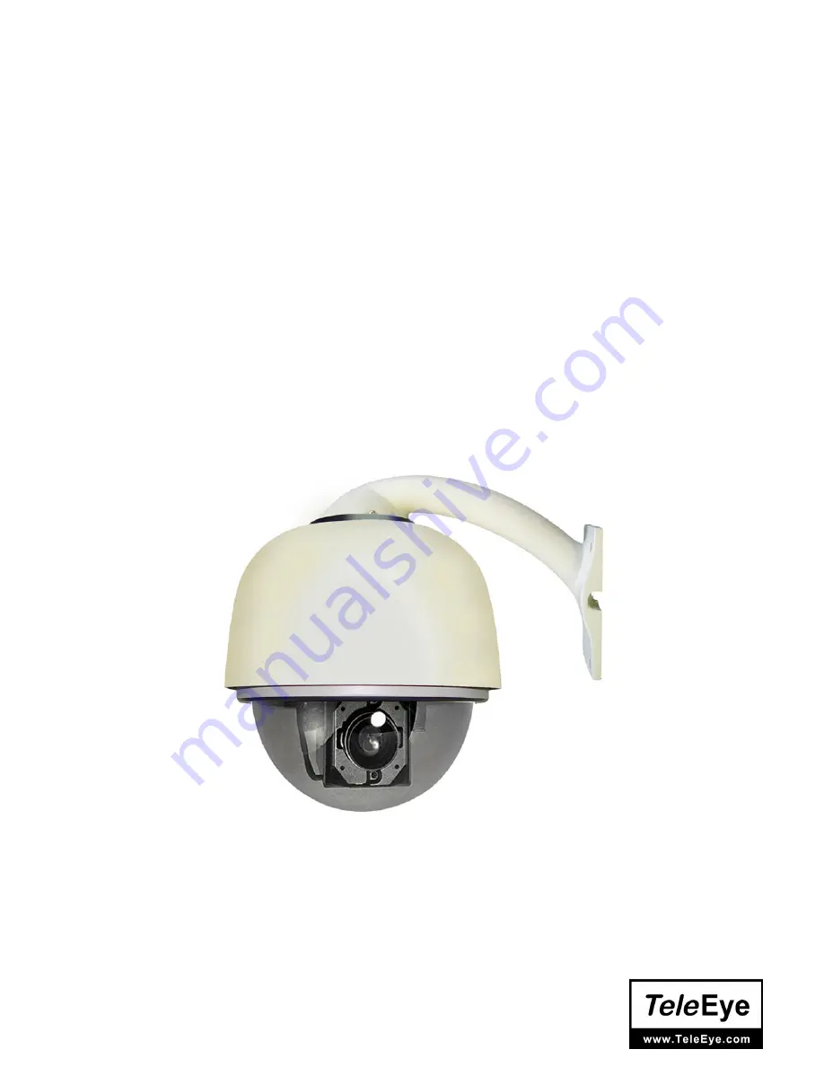
DM 567 / DM 569
High Speed Dome
Before attempting to intall or operate on this product,
please read this manual carefully and keep it for future use.
Страница 1: ...0 User Manual TeleEye DM 567 DM 569 High Speed Dome Before attempting to intall or operate on this product please read this manual carefully and keep it for future use...
Страница 2: ...Installation Instruction of the Acrylic Dome Shield 4 III Install Bend Tube Style Bracket 5 IV Description of Wiring 6 V Function Description 6 VI Function Setting 8 VII General Failure Analysis Table...
Страница 3: ...countries All other trademarks are the property of their respective owners Copyright c 2007 Signal Communications Limited A Member of TeleEye Group All rights reserved Version 2 0 Limits of Liability...
Страница 4: ...f and other protecting measures should be carried out 6 Please avoid exposing the Dome video camera to rain or the humidity etc Please do not use the product in humid place If the video camera is inst...
Страница 5: ...d to wear cotton gloves when operate 2 As shown in the figure below first take the flexible flat cable through connector above the base plate and buckle it on the connector Then buckle the cable on th...
Страница 6: ...5 III Install Bend Tube Style Bracket Fig 3 1 Connecting the dome to the wall mount with the bracket Fig 3 1 Wall mount bracket installation...
Страница 7: ...d from 0 5 240 degree sec continuously Vertical rotation range is 0 90 and rotation rate can achieve 60 degree sec b Low speed operation has features of stable ultra low noise and image without jitter...
Страница 8: ...ome device can scan between arbitrary two points within less than 180 and scanning speed is adjustable continuously related with communication protocols 3 Programmable six cruise tracks Each track has...
Страница 9: ...1 Location of the ID number dip switch and Protocol Baud rate dip switch 2 Address setting of Dome device first 8 digits of SW1 Coding Description Dome Address is represented in binary format where ON...
Страница 10: ...ice ID O represents ON switch state Dome Address ID Number 1 2 3 4 5 6 7 8 0 1 O 2 O 3 O O 4 O 5 O O 6 O O 7 O O O 8 O 9 O O 10 O O 11 O O O 12 O O 13 O O O 14 O O O 15 O O O O 16 O 17 O O 18 O O 19 O...
Страница 11: ......
Страница 12: ...Input the number S where S represents the tour sequence number 3 Press DELETE Auto Pan SCAN 0 ENTER Set auto pan left limit SCAN 1 ENTER Set auto pan right limit S SCAN Activate auto pan If S is with...
Страница 13: ...r contact Eliminate Self test is normal but there is no image Video camera is damaged Change Control signal line is connected mistakenly Correct Position of Dome device does not match Re select Self t...
Страница 14: ...ght 3 5Kg Installation Method Wall Pendant Pole Corner Mount Specification Operating Temperature 0 50 normal range Horizontal 0 240 s Vertical 0 60 s Preset position 50 Basic Function of Dome Scanning...