


U
SER
M
ANUAL
16
K
CL
M
ONO
–
R
EV
G
–
06/2017
P
A G E
|
23
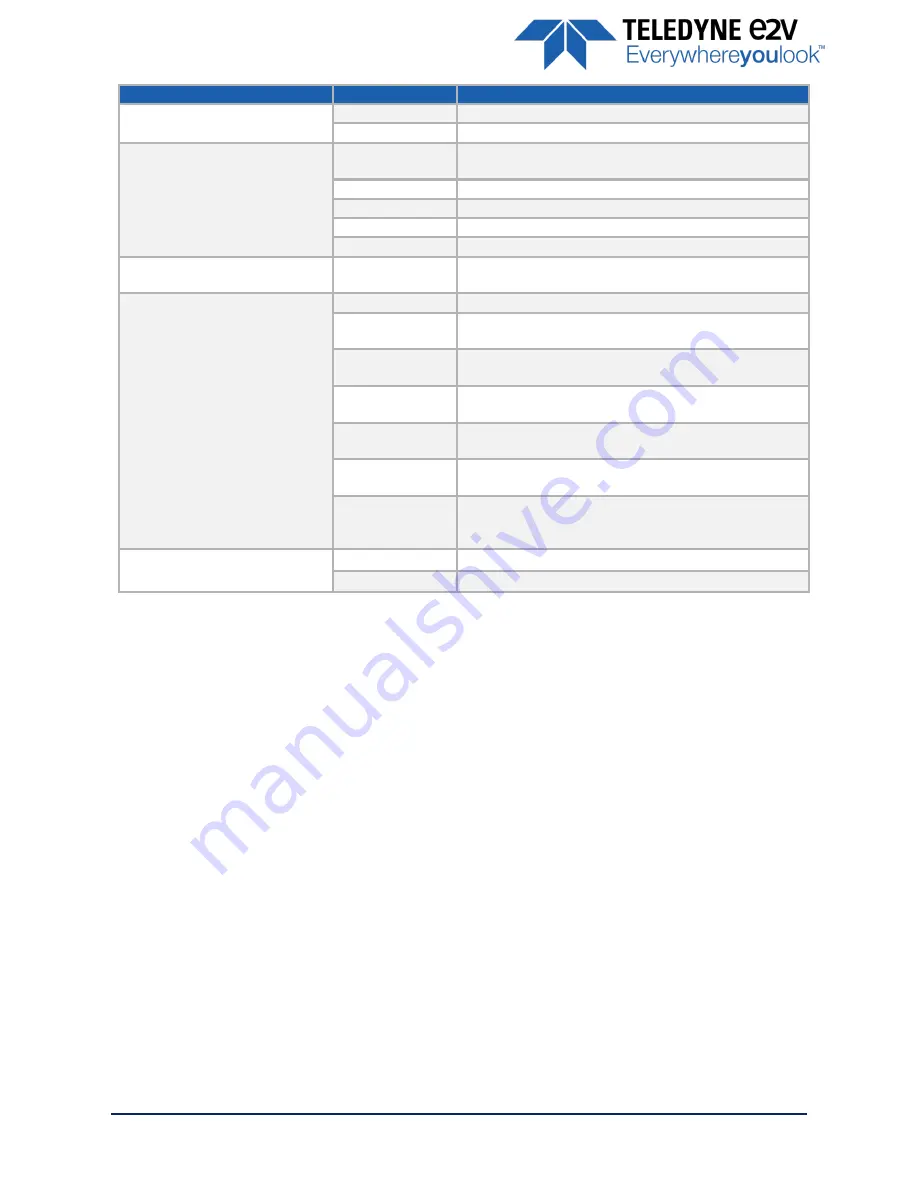
Feature
Command
Description
w revr 0
Set reverse reading to “disable”
w revr 1
Set reverse reading to “enable”
OutputMode
r mode
Get output mode (CameraLink configuration and CMOS
sensor resolution)
w mode 0
Set output mode to “Medium4Outputs8bits”
w mode 1
Set output mode to “Medium4Outputs12bits”
w mode 2
Set output mode to “Full8Outputs8bits”
w mode 3
Set output mode to “FullPlus10Outputs8bits”
OutputFrequency
r clfq
Get Camera Link frequency
TestImageSelector
r srce
Get test (output FPGA) image pattern
w srce 0
Set test (output FPGA) image pattern to “Off”, processing
chaine activated
w srce 1
Set test (output FPGA) image pattern to
“GreyHorizontalRamp”, processing chaine desactivated
w srce 2
Set test (output FPGA) image pattern to “White pattern”,
processing chaine desactivated
w srce 3
Set test (output FPGA) image pattern to “gray pattern”,
processing chaine desactivated
w srce 4
Set test (output FPGA) image pattern to “Black pattern”,
processing chaine desactivated
w srce 5
Set test (output FPGA) image pattern to
“GreyVerticalRampMoving”, processing chaine
desactivated
Output Centered ROI
r roiw
Return current ROI between 8192to 16384
w roiw <val>
Set new ROI Value between 8192to 16384 (No ROI)