background image


Genie_TS_Series GigE Vision Camera 

Using Genie TS with Sapera API  

  33 

GigE Server Status  

Once the Genie is assigned an IP address (its Status LED is steady blue) the GigE server tray icon 

will not have a red X through it, indicating that the Genie device was found. It might take a few 

seconds for the GigE Server to refresh its state after the Genie has obtained an IP address.  


Right-click the GigE Server tray icon to open the following menu.  


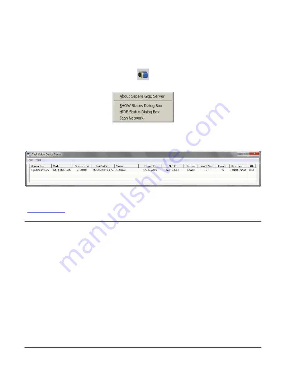
Click on Show Status to open a window listing all devices connected to the host system. Each GigE 

device is listed by name along with important information such as the assigned IP address and 

device MAC address. The screen shot below shows a connected Genie with no networking 

problems.  


In the event that the device is physically connected, but the Sapera GigE Server icon is indicating 

that the connected device is not recognized, click Scan Network to restart the discovery process. 

Note that the GigE server periodically scans the network automatically to refresh its state. See 

"Troubleshooting" on page 

175

 for network problems.   

Optimizing the Network Adapter used with Genie 

Most Gigabit network interface controllers (NIC) allow user modifications to parameters such as 

Adapter Buffers and Jumbo Frames. These should be optimized for use with the Genie during the 

installation. Refer to the 

Teledyne DALSA Network Imaging package manual

 for optimization 

information.   

Running the Network Configuration Tool 

The Network Configuration tool provides information and parameter adjustments for network 

adapters installed in the system and any connected GigE Vision camera without use of any 

Windows Control Panel application. This tool allows you to: 


Activate the Network Imaging driver use for image acquisition on any NIC or disable the 

imaging driver for any NIC not used with a GigE Vision camera.  


Change the Auto Discovery Interval from the default of 15 seconds. 


Verify that the GigE Server is in the Windows firewall exception list. 


Configure the NIC and camera IP settings. 


Assign a User Defined name to a connected camera. 


Assign a Persistent IP address to a camera instead of the default DHCP/LLA assigned address. 

Содержание TS-C2500

Страница 1: ...Genie TS Series Camera User s Manual Genie TS Framework 1 20 P N CA GENM TSM00 www teledynedalsa com sensors cameras frame grabbers processors software vision solutions...

Страница 2: ...s 7 are trademarks of Microsoft Corporation All other trademarks or intellectual property mentioned herein belong to their respective owners Document Date April 27 2015 Document Number CA GENM TSM00 C...

Страница 3: ...C1920 TS M2048 TS C2048 18 Sensor Specifications 18 Sensor Cosmetic Specifications 19 Spectral Response 20 SENSOR PERFORMANCE TS M2560 21 Sensor Specifications 21 Sensor Cosmetic Specifications 22 Spe...

Страница 4: ...ion Timing 57 Synchronous Mode 57 Reset Mode 57 Exposure Alignment Synchronous_EOE Reset_EOE 58 An Example Setup 58 Using Auto Brightness 58 General Preparation 58 Auto Brightness with Frame Luminance...

Страница 5: ...107 Width and Height Features for Partial Scan Control 112 Vertical Cropping Partial Scan 112 Maximum Frame Rate fps Examples TS M4096 DALSA Vouvray 113 Maximum Frame Rate fps Examples TS M3500 DALSA...

Страница 6: ...ILE ACCESS CONTROL CATEGORY 146 File Access Control Feature Descriptions 146 File Access via the CamExpert Tool 148 Overview of the deviceUserBuffer Feature 149 NETWORK OVERVIEW TOOLS 150 GENIE IP CON...

Страница 7: ...Network Parameters 177 Before Contacting Technical Support 177 INSTALLATION ISSUES AND FUNCTIONAL PROBLEMS 177 The Windows XP Firewall Service Can Not Start 177 Automatic Installation stalls when usi...

Страница 8: ...lighting conditions features to cycle a user defined sequence of imaging setups features to automatically adjust exposure and gain image transfer on demand plus both RS 485 and RS 232 ports all part...

Страница 9: ...increased sensitivity monochrome only Multiple lookup table pre processing for monochrome cameras Multiple real time Flat Field processing available with image cycling i e shading corrections Dynamic...

Страница 10: ...TS C1920 CMOSIS cmv2000 All Genie TS models ship with the Standard Design firmware except for TS M2560 which ships with the Fast Mode Design Alternative firmware designs are easily downloaded from th...

Страница 11: ...m 1 32 UN 2B CS C G2 GM10 T2041 G2 GM10 T2040 TS M2048 2048 x 2048 5 5 x 5 5 m 1 32 UN 2B CS C G2 GM12 T2041 G2 GM12 T2040 TS M1920 1920 x 1080 5 5 x 5 5 m 1 32 UN 2B CS C G2 GM10 T1921 G2 GM10 T1920...

Страница 12: ...Available for download http www teledynedalsa com mv Linux Package for Genie TS Contact Teledyne DALSA Sales Sapera Processing Imaging Development Library available for Windows or Linux sold separatel...

Страница 13: ...le provides a license free development platform for Teledyne DALSA GigE hardware or Sapera vision applications Additionally supported are Sapera GigE Vision applications for third party hardware with...

Страница 14: ...4 line monochrome models Gain Analog analog gain steps are model dependent and Digital gain up to 4x Counter and Timer 1 Counter and 1 Timer User programmable acquisition independent with event gener...

Страница 15: ...test EN61000 4 4 2004 Electrical fast transient burst immunity test EN61000 4 5 2005 Surge immunity EN61000 4 6 2008 Immunity to conducted disturbances induced by radio frequency fields EN61000 4 8 2...

Страница 16: ...posure modes External Exposure Control External pulse width plus 19 s for TriggerWidth exposure mode Internal Trigger to Start of Exposure 106 s minimum End of Exposure to Readout 20 s Horizontal Line...

Страница 17: ...ck at 0 and maximum saturated value Spot defects none Grouping of more than 8 pixel defects within a sub area of 3x3 pixels to a maximum spot size of 7x7 pixels Clusters defects none Grouping of more...

Страница 18: ...550 600 650 700 750 800 850 900 Wavelength nm Responsivity DN nJ cm 2 Effective Quantum Efficiency Monochrome The quantum efficiency graph describes the fraction of photons at each wavelength that con...

Страница 19: ...0 900 Wavelength nm Responsivity DN nJ cm 2 Effective Quantum Efficiency Color Effective Spectral Quantum Efficiency Gain Analog 1 0 0 5 10 15 20 25 30 35 40 400 450 500 550 600 650 700 750 800 850 90...

Страница 20: ...JPEG Firmware all models 7 s for Fast Design Firmware all supported models Maximum 16 sec for all models and firmware Internal Trigger to Start of Exposure 0 s External Exposure Control External puls...

Страница 21: ...5 Max 0 005 Any pixel that deviates by 20 from the average of neighboring pixels at 50 saturation including pixel stuck at 0 and maximum saturated value Spot defects none Grouping of more than 8 pixel...

Страница 22: ...d on 12 m epi layer wafers As seen in the following graph E12 sensors have an increased spectral response above 600nm 5 m epi layer wafer models G2 GM10 T1921 G2 GM10 T2041 12 m epi layer wafer models...

Страница 23: ...Start of Exposure 0 s External Exposure Control External pulse width plus 97 s TS M2560 TriggerWidth exposure mode End of Exposure to Start of Readout 63 s for TS M2560 Horizontal Line Time 12 9 s Re...

Страница 24: ...more than 8 pixel defects within a sub area of 3x3 pixels to a maximum spot size of 7x7 pixels Clusters defects none Grouping of more than 5 single pixel defects in a 3x3 kernel Column defects none Ve...

Страница 25: ...sors response at 1500 s exposure with nominal gain 35 52 70 87 45 64 85 105 80 118 156 194 0 32 64 96 128 160 192 224 256 4 19 6 25 8 38 10 46 Light power W cm 2 Signal DN 8 bits VOUVRAY Nominal Gain...

Страница 26: ...and memory sizes PAUSE Frame support is typically required to manage network traffic within an Ethernet switch when multiple cameras are simultaneously used Using PAUSE Frame will require the user to...

Страница 27: ...computer Gigabit NIC The Genie TS also supports Power Over Ethernet PoE See Ruggedized RJ45 Ethernet Cables on page 173 for secure cables A Micro D sub 25 connector for camera power or auxiliary powe...

Страница 28: ...will it be possible by the GigE Server or any application to communicate with the camera The following table summarizes the LED states and corresponding camera status LED State Definition LED is off N...

Страница 29: ...guration Mode Details on page 150 Supported Network Configurations The Genie obtains an IP address using the Link Local Address LLA or DHCP by default A LLA IP address is obtained in about 6 seconds w...

Страница 30: ...ne is not necessarily connected to earth ground Teledyne DALSA has performed ESD testing on Genie cameras using an 8 kilovolt ESD generator without any indication of operational faults The two followi...

Страница 31: ...apera or Sapera runtime is not required and you need to follow the installation instructions of the third party package Install the Genie Framework software package if not using a third party GigE Vis...

Страница 32: ...es the Network Imaging package refer to the Teledyne DALSA Network Imaging package manual When using a third party GigE Vision network driver the Network Imaging package is not required unless you nee...

Страница 33: ...e for the various Genie TS models and where the xx in the file name denotes the firmware build version Current version firmware files are posted on the Teledyne DALSA support web site DALSA Vouvray mo...

Страница 34: ...e installation the GigE Server icon is visible in the desktop taskbar tray area note that in Windows 7 the icon remains hidden until a camera is connected After connecting a camera see following secti...

Страница 35: ...ork automatically to refresh its state See Troubleshooting on page 175 for network problems Optimizing the Network Adapter used with Genie Most Gigabit network interface controllers NIC allow user mod...

Страница 36: ...o user defined name has been assigned Quick Test with CamExpert When the Genie TS camera is connected to a Gigabit network adapter on a host computer testing the installation with CamExpert is a strai...

Страница 37: ...Expert feature selection and the grabbed pattern are shown below Note that CamExpert cannot be used to grab at high frame rates due to it generating an interrupt for each video frame The Sapera Grab D...

Страница 38: ...xample Non Teledyne DALSA cameras are labeled as GigEVision Device Click on a device user name to select it for control by CamExpert An imaging application uses any one of these attributes to identify...

Страница 39: ...ss which is saved in the windows folder One simple method is to execute the Framework installer from within a batch file The batch file will have one command line As an example using the possible exec...

Страница 40: ...ed SaperaGenie xml Configuration for Sapera LT Sapera Processing and Teledyne DALSA Genie devices These files are located in the following directories Install Directory Sapera Install Win7_Embedded Wi...

Страница 41: ...acquisition display window which allows immediate verification of timing or control parameters without the need to run a separate acquisition program Click on any parameter and a short description is...

Страница 42: ...g all acquisition parameters supported by the acquisition device CamExpert displays parameters only if those parameters are supported by the installed device This avoids confusion by eliminating param...

Страница 43: ...es required for basic operation of the device to Guru optional features required only for complex operations CamExpert presents camera features based on their visibility attribute CamExpert provides q...

Страница 44: ...ibute and in which device version the feature was introduced Additionally the Device Version column will indicate which parameter is a member of the DALSA Features Naming Convention indicated by DFNC...

Страница 45: ...inner Device Temperature DeviceTemperature The temperature of the selected source in degrees Celsius 1 11 Beginner Power up Configuration Selector UserSetDefaultSelector Selects the camera configurati...

Страница 46: ...Displays the Device Acquisition Type of the product RO Sensor Sensor The device gets its data directly from a sensor 1 00 DFNC Invisible Device TL Type DeviceTLType Transport Layer type of the device...

Страница 47: ...n state to load on power up see feature UserSetDefaultSelector The user chooses from one factory data set or one of two possible user saved states User Set Configuration Management The second drop lis...

Страница 48: ...re read only either always or due to another parameter being disabled Parameters in black are user set in CamExpert or programmable via an imaging application Features listed in the description table...

Страница 49: ...e Feature Values Description Vouvray DALSA CMOSIS CMV xx AnaFocus Lince 5M Device Scan Type DeviceScanType Defines the scan type of the device s sensor Genie TS is an Areascan camera RO Beginner All D...

Страница 50: ...age grayscale value in DN for the auto brightness algorithm Features that use auto brightness include ExposureAuto GainAuto and IrisAuto DFNC Expert V1 10 all all all Auto Brightness Target Variation...

Страница 51: ...tness ROI Mode is set to Off DFNC Expert all all all Off Off The output image is used in the Auto Brightness algorithm Active Active The selected ROI is used in the auto brightness algorithm Auto Brig...

Страница 52: ...to the sensor capabilities and current frame trigger DFNC Beginner all all all Synchronous Synchronous Exposure is synchronous to the internal timing of the sensor The readout is concurrent to the ex...

Страница 53: ...r Selects which gain is controlled when adjusting gain features Beginner all all all Analog AnalogAll Apply an analog gain adjustment within the sensor to the entire image Digital DigitalAll Apply a d...

Страница 54: ...Cmd Enables an automatic black level adjustment process Expert V1 xx Automatic Black Level Calibration Status BlackLevelAutoCalibrationStatus Returns the current state of black level calibration Exper...

Страница 55: ...Acquisition Frame Rate Raw AcquisitionFrameRateRaw Controls the desired frame rate of the camera in 001 Hz Invisible all all all Black Level RAW BlackLevelRaw Controls the black level as an absolute...

Страница 56: ...eatures and limitations are described below Black Level offset is expressed as a digital number providing a offset from the factory setting The factory setting optimized the black level offset for max...

Страница 57: ...the external trigger pulse width when the feature ExposureMode TriggerWidth as shown in the following graphic Internal Programmable Exposure The Genie TS in an Internal Programmable Exposure mode has...

Страница 58: ...adout must be sequential limiting the maximum frame rate Exposure duration is programmable from the model dependent minimum to 16 seconds in 1 s steps Any external trigger received before the last exp...

Страница 59: ...up to its maximum frame rate Any trigger received before the start of frame readout is ignored and generates an invalid frame trigger event Since the external trigger is asynchronous with the Genie ho...

Страница 60: ...ter how short or long the actual exposure was Using Auto Brightness The Auto Brightness features are designed to maintain consistent brightness or image intensity in situations where lighting varies T...

Страница 61: ...ired in imaging situations where the frame rate must not be forced below some minimum value Also check that exposureAutoMinValue is low enough to allow the auto exposure a wide range to function in bu...

Страница 62: ...ght intensity number of photons and the digital gray level number DN output But situations exist where a proper exposure for most of an image will also include areas that are fully saturated overexpos...

Страница 63: ...e such that pixels similar to curve 2 are not saturated would reduce the gray level of pixels such as curve 3 This solution often is not acceptable The Multi Slope feature can effectively extend the d...

Страница 64: ...r to make multiple changes to converge to a solution Only pixels with DN values exceeding the setting for multiSlopeKneePositionY within the user set exposure time will be affected by the multi slope...

Страница 65: ...at the user requires the multi slope feature to act on At the multiSlopeKneePositionY setting the sensitivity is reduced until the multiSlopeKneePositionX setting where sensitivity returns to normal W...

Страница 66: ...when enabled therefore increasing the pixel well capacity at the sensor level When used with a color camera white balance will not be correct above the knee point Example Procedure for Multi Slope Se...

Страница 67: ...h as a camera outdoors the two multi slope variables and the camera iris will need dynamic adjustments to maintain image quality I O Control Category The Genie TS I O controls as shown by CamExpert gr...

Страница 68: ...ames to acquire when a valid trigger is received This feature is R W only whenTriggerSelector FrameBurstStart The trigger frame count includes the number of frames specified in the Pre Trigger Frame C...

Страница 69: ...l line Output 1 Associated with the logical line Output 2 Associated with the logical line Output 3 Associated with the logical line Output 4 1 00 Beginner DFNC Line Pinout linePinAssociation Enumerat...

Страница 70: ...he state of the output Pulse on Start of Frame PulseOnStartofFrame Generate a pulse on the start of the Frame Active event Pulse on Start of Exposure PulseOnStartofExposure Generate a pulse on the Exp...

Страница 71: ...outputLineSoftwareCmd 1 00 Guru DFNC Output Line Software Command outputLineSoftwareCmd Writing a value of 1 in the bit field applies the Latch value of the outputLineSoftwareLatchControl and or exec...

Страница 72: ...rnal trigger signal where the specific input line is selected by the Trigger Source feature External signals are isolated by an opto coupler input with a time programmable debounce circuit Trigger Sou...

Страница 73: ...s are connected to I O lines 5 through 8 and have the following features for control or status indication Feature set LineInverter RW outputLineSource RW outputLinePulseDelay RW outputLinePulseDuratio...

Страница 74: ...in a number of models implementing different sensors and image resolutions which may not support the full feature set defined in this category Counter and Timer Control Feature Description The follow...

Страница 75: ...tarts on the reception of the Acquisition Start event Acquisition End AcquisitionEnd Counter starts on the reception of the Acquisition End event Exposure Start ExposureStart Counter starts on the rec...

Страница 76: ...umber of transitions on Line 4 based on the counterIncrementalLineActivation feature setting Internal Clock InternalClock The counter increments on each microsecond tick of the device internal Clock T...

Страница 77: ...ector timerSelector Selects which timer to configure Timer 1 Timer1 Timer 1 selected 1 00 Expert DFNC Timer Mode timerMode Select the timer mode The selected Timer is Active or Disabled When Disabled...

Страница 78: ...ge Starts counter on the falling or rising edge of the selected signal 1 00 Expert DFNC Timer Delay timerDelay Sets the duration in microseconds of the delay to apply at the reception of a trigger bef...

Страница 79: ...Event or CounterEnd the counter is reset to 00 but does not restart counting until the next CounterReset Cmd Example Counter Start Source CounterEnd itself Counter starts when Counter Mode is set to...

Страница 80: ...78 Operational Reference Genie_TS_Series GigE Vision Camera Example CounterStartSource EVENT and Signal Edge Base Example CounterStartSource Signal Level Base Example 1...

Страница 81: ...Genie_TS_Series GigE Vision Camera Operational Reference 79 Example CounterStartSource Line Edge Base Example 2...

Страница 82: ...ter device version Parameters in gray are read only either always or due to another parameter being disabled Parameters in black are user set in CamExpert or programmable via an imaging application Fe...

Страница 83: ...on Vouvray DALSA CMOSIS CMV xx AnaFocus Lince 5M Flat Field Correction Mode flatfieldCorrectionMode Sets the mode for the Flat Field correction Beginner DFNC All Designs V1 11 STD V1 20 JPG Off Off Fl...

Страница 84: ...l Y Coordinate flatfieldCorrectionPixelYCoordinate Specifies the Y coordinate of the flat field pixel coefficient to access Guru DFNC all V1 11 STD V1 20 JPG Flat Field Correction Pixel X Coordinate f...

Страница 85: ...minimum DN difference between a pixel in the bright and its neighborhood before it s tagged as defective Expert DFNC V1 10 all STD Fast Automatic White Balance BalanceWhiteAuto Controls the mode for a...

Страница 86: ...Sets the color correction feature to manual or automatic Expert DFNC V1 20 V1 20 Off Off The RGB gains are manually controlled using the Gain feature Active Active The RGB gains are automatically con...

Страница 87: ...nochrome cameras Requires an acquisition of 4 lines minimum Expert DFNC STD STD Off Off Disables Image Sharpness feature Active Active Enables Image Sharpness feature Sharpness Type sharpnessType Sele...

Страница 88: ...xel all all LUT Index LUTIndex Selects the index offset of the coefficient to access in the selected LUT Guru all all LUT Value LUTValue Returns the value at specified LUT index entry of the LUT selec...

Страница 89: ...uffer Width flatfieldAlgorithmBufferWidth Internal use for Sapera FFC Class library RO Invisible DFNC all STD Flat Field Algorithm Buffer Height flatfieldAlgorithmBufferHeight Internal use for Sapera...

Страница 90: ...ie_TS_Series GigE Vision Camera Factory Preset FactoryPreset Loads the factory color enhancement coefficient set as the active set User Defined UserDefined Loads a user defined color enhancement coeff...

Страница 91: ...2 0 1 0 2 3 1 0 2 2 1 0 2 1 1 0 2 3 1 0 2 2 1 0 2 1 1 0 2 0 2 1 0 3 O u t p u t C ir c u it S e n s o r A D C ir c u it P i x e l D a t a S i m p lif ie d G e n ie T S L U T B lo c k D i a g r a m 1 0...

Страница 92: ...conditions This allows users to store FFC data for different optimized exposure setups Correction Function Block Diagram The following simplified block diagram shows that sensor data can have FFC appl...

Страница 93: ...bottom half A Sapera application saves the new buffer using SapBuffer Save with the format tiff option which allows saving data without loss of significant bits Note If the offset data 0xff then that...

Страница 94: ...xel is compared with its 3x3 neighborhood If a dark pixel is more different than its neighbors by the value of defectivePixelDetectionMinDarkThreshold then it is replaced If a bright pixel is more dif...

Страница 95: ...abbing a very dark image Indicates one or more hot pixels Average dark pixel value Important In this example the average pixel value for the frame is close to black Also note that most sensors will sh...

Страница 96: ...to light over the full dynamic range specified for that sensor Once the bright gray acquisition setup is done note the camera position and lens iris position so as to be able to repeat it during the...

Страница 97: ...erence images are valid a histogram tool is provided so that the user can review the images used for the correction data Note that it is important to follow the instructions in the preceding section t...

Страница 98: ...ge but not saturated white Even illumination on white paper can be used with a gray level of minimum of 128 8 bit mode It is preferable to prepare for the white level calibration step before starting...

Страница 99: ...mware is loaded The Compression Rate feature ImageCompressionRateOption is currently set to Fixed Quality where the output image has a non varying quality Alternative image quality options may be avai...

Страница 100: ...between camera states thus ensuring immediate camera response A setup example follows the feature table Parameters in gray are read only either always or due to another parameter being disabled Parame...

Страница 101: ...Preset Mode cyclingPresetMode Sets the Cycling Presets module mode Expert DFNC V1 10 All Designs V1 10 All Designs V1 20 Fast Off Off Disable the Cycling Preset module Active Active Enable the Cycling...

Страница 102: ...osition The cP_FeaturesActivationMode feature will control ROI position all all all Output Lines OutputLineControl The cP_FeaturesActivationMode feature controls the output lines all Fast Black Level...

Страница 103: ...se This feature is only used when the currently selected cycling preset is active Expert DFNC all all all Luminance 1 Luminance1 Sets the current LUT as Luminance 1 Luminance 2 Luminance2 Sets the cur...

Страница 104: ...validFrameTrigger Generate a pulse on the Invalid FrameTrigger event Pulse On Start of Acquisition PulseOnStartofAcquisition Generate a pulse when the AcquisiontStart event occurs Pulse On End of Acqu...

Страница 105: ...Vertical offset from the origin to the region of interest ROI The value in this feature is only used when the currently selected cycling preset is active Expert DFNC all all all Black Level RAW cP_Bla...

Страница 106: ...ogical choice in a free running acquisition setup Set the feature cyclingPresetRepeater to the number of incremental source events to count before switching to the next preset In this example we are c...

Страница 107: ...owed by a Long Exposure A second cycling example uses an external trigger to initiate a single short exposure followed by a single long exposure A brief outline is presented here As was suggested for...

Страница 108: ...etup without a lens Parameters in gray are read only either always or due to another parameter being disabled Parameters in black are user set in CamExpert or programmable via an imaging application F...

Страница 109: ...r Display Name Feature Values Description Vouvray DALSA CMOSIS CMV xx AnaFocus Lince 5M Data Stream Selector dataStreamSelector Select which data stream to control default is Stream 1 RO Expert DFNC A...

Страница 110: ...ture The ROI Count is set by the Multiple ROI Count feature Expert DFNC V1 20 STD V1 20 Fast Off Off Single ROI per image Active Active The ROI per image feature is active ROI Count Horizontal multipl...

Страница 111: ...V1 20 JPG V1 00 STD V1 20 JPG In Sensor InSensor The Binning function can be done inside the Sensor itself which often allows binning to increase the data rate from the sensor In Digital Domain InDigi...

Страница 112: ...rom the darkest possible value to the brightest by 1 Dn increment per frame Grey Diagonal Ramp GreyDiagonalRamp Image is filled horizontally and vertically with an image that goes from the darkest pos...

Страница 113: ...MonoPacked MonoPacked Pixel is monochrome and packed Raw Bayer Raw Pixel is raw Bayer RGB Packed RGBPacked Pixel is RGB packed STD STD BGRA Packed BGRAPacked Pixel is BGRA 32 bit STD STD YUV422 Packe...

Страница 114: ...up to the Genie TS model maximum The following figure is an example of a partial scan acquisition using both Height and Vertical Offset controls The Vertical Offset feature defines at what line number...

Страница 115: ...DALSA Vouvray Vertical Lines Acquired Free Running Acquisition Synchronous Mode 20 s exposure Triggered Acquisition Reset Mode 20 s exposure 2200 19 fps 19 fps 1500 28 fps 28 fps 750 57 fps 57 fps 37...

Страница 116: ...6 583 1164 64 1111 2212 1126 2242 32 2053 4065 2105 4166 16 3558 6993 3717 7299 8 5617 10989 6024 11764 4 7936 15384 8771 16949 2 10000 19230 11363 21739 Maximum Frame Rate fps Examples TS M1920 CMOSI...

Страница 117: ...1 2 4907 3960 Horizontal Cropping Partial Scan Genie TS supports cropping the acquisition horizontally by grabbing less pixels on each horizontal line Horizontal offset defines the start of the acquir...

Страница 118: ...rate The following graphic illustrates binning 1 640 639 4 3 2 1 2 320 Horizontal Binning by 2 Line 1 Line 2 Line 3 Line 4 Line 479 Line 480 Line 1 Line 2 Line 240 Repeated for each line of pixels Re...

Страница 119: ...cally with an image that goes from the darkest possible value to the brightest Grey Diagonal Ramp Moving combination of the 2 previous schemes but first pixel in image is incremented by 1 between succ...

Страница 120: ...he constraints when configuring the ROI areas Example Two Horizontal ROI Areas 2x1 ROI x1 y1 ROI x2 y1 ROI x1 y1 ROI x2 y1 2 ROI Areas Defined Camera Outputs only the 2 ROI Areas Note that ROI x1 y1 d...

Страница 121: ...is example uses the example problem of solder inspection of certain components on a PCB The image below of a sample PCB shows 6 ROI areas highlighted by the yellow overlay graphics manually added to t...

Страница 122: ...t tagged as Invisible are usually for Teledyne DALSA or third party software usage not typically needed by end user applications Also important Genie TS cameras are available in a number of models imp...

Страница 123: ...uring the image acquisition to the metada attached to the image cyclingPresetCurrentActiveSet Add the cyclingPresetCurrentActiveSet value used during the image acquisition to the metada attached to th...

Страница 124: ...the data structure to access the Genie TS image metadata Function Description DALSA_GENIE_CHUNK_Extract void pRawChunk UINT32 rawSize DALSA_GENIE_CHUNK_INFO pChunkInfo parameters pRawChunk Pointer to...

Страница 125: ...during an acquisition and the way the acquisition stops Single Frame SingleFrame One frame is captured for each AcquisitionStart Command An AcquisitionStop occurs at the end of the Active Frame Multi...

Страница 126: ...ng of data Block s to another device 1 10 Expert Transfer Abort TransferAbort Aborts the streaming of data Block s to another device 1 10 Expert Device Registers Streaming Start DeviceRegistersStreami...

Страница 127: ...If the SDK is based on GenAPI 2 3 or lower the user must call the command DeviceFeaturePersistenceStart before using the SDK Save Camera method and the command DeviceFeaturePersistenceEnd at the end o...

Страница 128: ...us or a specific image frame count MultiBlock The transfer frame count is set by the feature TransferBlockCount which must be equal or less than the number of image frames available in the camera s ci...

Страница 129: ...ROL NA ADVANCED PROCESSING CONTROL flatfieldCorrectionMode CYCLING PRESET MODE CONTROL cyclingPresetMode cP_FeaturesActivationMode cP_FlatfieldCorrectionMode IMAGE FORMAT CONTROL PixelFormat OffsetX O...

Страница 130: ...eter being disabled Parameters in black are user set in CamExpert or programmable via an imaging application Features listed in the description table but tagged as Invisible are usually for Teledyne D...

Страница 131: ...d I O control block to use as the timestamp increment source 1 00 Expert DFNC Timestamp Tick Frequency in Hz timestampTickFrequency Indicates the number of timestamp ticks or increments during 1 secon...

Страница 132: ...due to insufficient onboard memory Events Overflow eventsOverflow Event sent on control channel when all previous active events have been disabled because the camera cannot send them fast enough gene...

Страница 133: ...esents the event ID to identify the valid frame trigger RO 1 00 Guru Valid Frame Trigger Event Timestamp EventValidFrameTrigger Timestamp Timestamp of the Valid frame trigger event RO 1 00 Guru Invali...

Страница 134: ...ws the primary events related to a simple acquisition Frame Inactive Frame Inactive Exposure ReadOut Exposure Delay Events Associated with Triggered Synchronous Exposures The following timing graphic...

Страница 135: ...ws the primary events and acquisition timing associated with reset exposure of two frames FrameActive 1 Frame Inactive FrameTrigger Inactive TriggerDelay FrameActive 2 FrameTrigger Active Exposure 1 R...

Страница 136: ...are available in a number of models implementing different sensors and image resolutions which may not support the full feature set defined in this category GigE Vision Transport Layer Feature Descri...

Страница 137: ...set to Persistent IP static DHCP DHCP Device IP Address Configuration is set to DHCP Dynamic Host Configuration Protocol Network requires a DHCP server LLA LLA Device IP Address Configuration is set...

Страница 138: ...image or chunk on the stream channel RO 1 00 Invisible MAC Address GevMACAddress MAC address of the network interface RO 1 00 Invisible Current Camera IP Configuration GevCurrentIPConfiguration Curren...

Страница 139: ...turns TRUE if the selected GEV option is supported RO 1 00 Invisible LLA Supported GevSupportedIPConfigurationLLA Indicates if LLA Auto IP is supported by the selected interface The LLA method automat...

Страница 140: ...URL GevSecondURL Indicates the second URL to the XML device description file RO 1 00 Invisible Gev Major Version GevVersionMajor Major version of the specification RO 1 00 Invisible Gev Minor Version...

Страница 141: ...Height are used because the Width and Height values can change if binning is used or even while grabbing Device UPnP Auto Discovery Mode Details The Genie TS supports UPnP Network Auto Discovery Unive...

Страница 142: ...creen capture Note that the discovery process is usually fast but may take up to 10 seconds tested on a Windows 7 pc and this delay must be accounted for by any application activating the deviceUPnPDi...

Страница 143: ...or all of the Genie TS file memory is usable by the user to store data Folders can be created and files copied to the camera limited to available space Any factory distribution files or folders can be...

Страница 144: ...major device version release will be indicated by green text for easy identification Display Name Feature Values Description Device Version View Serial Port Selector DeviceSerialPortSelector Selects t...

Страница 145: ...in Micro D connector where one supports RS 232 signals while the second supports RS 485 see 25 pin Micro D type Connector Details Note that this document does not cover the choice of one serial standa...

Страница 146: ...emote Serial Port Control menu item Automatic Windows Driver Installation The first time the remote serial port control is enabled on a system an automatic Windows driver update executes as shown in t...

Страница 147: ...Baud rate is variable within the software control s capabilities With the Port Control set to InCameraControlled port parameters are set by Genie TS features as defined in this section Windows XP pro...

Страница 148: ...sion View File Selector FileSelector Selects the file to access The file types which are accessible are device dependent Firmware Firmware1 Upload new firmware to the camera which will execute on the...

Страница 149: ...s mode used to open a file on the device Read Read Select READ only open mode Write Write Select WRITE only open mode 1 00 Guru File Access Buffer FileAccessBuffer Defines the intermediate access buff...

Страница 150: ...om the file type drop menu select the file type that will be uploaded to the Genie TS This CamExpert tool allows quick firmware changes or updates when available for your Genie TS model From the File...

Страница 151: ...e a device reset command from the Camera Informtion Controls Overview of the deviceUserBuffer Feature The feature deviceUserBuffer allows the machine vision system supplier access to 4 kB of reserved...

Страница 152: ...he DHCP server Windows will turn to LLA when no DHCP server answers requests coming from the NIC Windows XP takes about 1 minute to obtain an LLA IP address Windows Vista 7 will take about 6 seconds W...

Страница 153: ...additional subnet Under Windows a NIC is configured in DHCP mode by default If no DHCP server is present on a given subnet Windows will revert to LLA as explained in the section above Ensure that a d...

Страница 154: ...A mode The camera MAC address must be known to use this function For GigE Vision applications the FORCEIP command is used to force a new persistent IP or to change the IP configuration protocol The Ge...

Страница 155: ...nie_TS_Series GigE Vision Camera Technical Specifications 153 Technical Specifications Mechanical Specifications TS M4096 TS M3500 TS M2500 TS C4096 TS C3500 TS C2500 Note Genie TS with M42x1 Lens Mou...

Страница 156: ...s Genie_TS_Series GigE Vision Camera M42x1 to Nikon F Bayonet Adapter See Lenses for the Genie TS with M42 or with Nikon F mount for information on lens selection relative to Genie TS model used Nikon...

Страница 157: ..._TS_Series GigE Vision Camera Technical Specifications 155 M42x1 to C Mount Adapter See Lenses for the Genie TS 5M with the optional C Mount Adapter for information on lens selection M42 to C Mount Ad...

Страница 158: ...Specifications Genie_TS_Series GigE Vision Camera Mechanical Specifications TS M1920 TS M2048 See Lenses for the Genie TS with CS Mount 2M or 4M for information on lens selection Note Genie TS with C...

Страница 159: ...cations which provide good grounding capabilities Overall height or width tolerance is 0 05mm Sensor Alignment Specification The following figure specifies sensor alignment for Genie TS where all spec...

Страница 160: ...4 Volts 3 RSV Reserved 4 Lens GND Lens Common Ground 5 Lens Zoom Out Lens Motor Zoom 6 Lens Zoom Out Lens Motor Zoom 7 Lens Focus Out Lens Motor Focus 8 Lens Focus Out Lens Motor Focus 9 Lens Iris Out...

Страница 161: ...hernet power injector The Genie TS is protected and will not fail in the case of have both an external supply and PoE connected at the same time If both supplies are connected and active the Genie wil...

Страница 162: ...onLevel feature Used as trigger acquisition event counter or timestamp event or integration control User programmable debounce time from 0 to 255 s in 1 s steps Source signal requirements Single ended...

Страница 163: ...de to computer and networking equipment required to support the Genie camera at maximum performance The Genie camera series complies with the current IPv4 Internet Protocol therefore current Gigabit E...

Страница 164: ...smitted through the switch to the NIC efficiently without data loss As a working example one such switch tested at Teledyne DALSA is the NETGEAR GS716T Important The maximum frame rate possible from a...

Страница 165: ...Genie_TS_Series GigE Vision Camera Technical Specifications 163 EC FCC Declarations of Conformity Models TS M4096 TS C4096 TS M3500 TS C3500 TS M2500 TS C2500...

Страница 166: ...164 Technical Specifications Genie_TS_Series GigE Vision Camera Models TS M1920 TS C1920 TS M2048 TS C2048...

Страница 167: ...Genie_TS_Series GigE Vision Camera Technical Specifications 165 Model TS M2560...

Страница 168: ...sure even illumination from the lens used Genie TS cameras with CS mounts can use optional C mount lens adapters The following sections describe the image size requirement for the different Genie TS m...

Страница 169: ...uires the Genie TS M42 to C Mount Lens Adapter G2 AM42 MOUNT0 The following graphic shows the relative image circle sizes of typical 1 and 1 3 machine vision C Mount lenses when used with a 5 megapixe...

Страница 170: ...oosing lenses since there is a trade off between the best lenses and cost An abridged list of lens parameters follows all of which need to be matched to the application Focal Length Defines the focus...

Страница 171: ...ources are relatively inexpensive provide a uniform field and longer life span compared to other light sources However they also require a camera with excellent sensitivity Halogen light sources gener...

Страница 172: ...ce Information Genie_TS_Series GigE Vision Camera The graphic below shows a sample response of a Genie TS color camera with an overlay of a cutoff filter suppressing wavelengths above 650nm from reach...

Страница 173: ...the lens surface to the second focal point The object distance OD is the distance from the first principal point to the object Primary Points in a Lens System Magnification and Resolution The magnific...

Страница 174: ...th and should be handled like other optical components with extreme care Dust can obscure pixels producing dark patches on the sensor response Dust is most visible when the illumination is collimated...

Страница 175: ...essed air cannot clean the sensor Dalsa recommends using lint free ESD safe cloth wipers that do not contain particles that can scratch the window The Anticon Gold 9 x 9 wiper made by Milliken is both...

Страница 176: ...ed for near end far end crosstalk and return loss IGE 3M 3meters IGE 10M 10meters IGE 25M 25meters IGE 50M 50meters IGE 100M 100meters For Information contact Components Express Inc CEI 10330 Argonne...

Страница 177: ...E server tray icon when the Genie device is not found This indicates a network issue where there is no communication with Genie Or in the simplest case the Genie is not connected The GigE server tray...

Страница 178: ...A Network Imaging manual When using multiple cameras connected to an VLAN Ethernet switch confirm that all cameras are on the same subnet setup on that switch See the Teledyne DALSA Network Imaging pa...

Страница 179: ...rogram From its File menu click on Save Messages to generate a log text file Report the version of Genie TS Framework and Sapera version used Installation Issues and Functional Problems This section c...

Страница 180: ...A engineering follow the instructions in Appendix A Framework Installation Issues with Foreign Language Windows Device Available with Operational Issues This section considers issues with cabling Ethe...

Страница 181: ...n the Genie is in a high vibration environment See Ruggedized RJ45 Ethernet Cables on page 173 Check the Ethernet status LEDs on the Genie RJ45 connector The Link Status indicator is on and the activi...

Страница 182: ...tool has limits to the maximum frame rate possible due to CamExpert generating an interrupt for each acquired frame The Sapera Grab Demo may be better suited for testing at higher frame rates Verify...

Страница 183: ...ter use Sapera LT version 7 50 or later for decoding acquisitions by the JPEG firmware design Issues with Cognex VisionPro When the Cognex VisionPro package is uninstalled the Genie TS becomes not ava...

Страница 184: ...Windows there is a problem where the installation of a required filter driver does not proceed automatically Until this issue is resolved by Teledyne DALSA engineering a user needs to follow the inst...

Страница 185: ...anguage Windows 183 Select the local directory as shown in the following dialog Note that this image is for a Windows 64 installation When using a Windows 32 computer the folder path is Win32 inf With...

Страница 186: ...Framework Installation Issues with Foreign Language Windows Genie_TS_Series GigE Vision Camera Click OK to accept this file Finally select and click OK to load the driver Teledyne DALSA Sapera Network...

Страница 187: ...ows 185 After this step the installation will progress automatically as is normal with the English version of Windows These manual steps by the user in no way affect the installation but are simply a...

Страница 188: ...ax 978 670 2010 Teledyne DALSA GMBH Lise Meitner Str 7 82152 Krailling Munich Germany Tel 49 89 89545730 Fax 49 89 895457346 sales europe teledynedalsa com Asian Sales Teledyne DALSA Asia Pacific Ikeb...

Страница 189: ...ic LED 24 Digital Gain 54 Dust problems 172 dynamic range 60 E Edge Pre select 56 effective focal length 171 electrostatic discharge 28 embedded processing 89 Embedded support 38 ESD testing 28 Ethern...

Страница 190: ...x1 lens screw mount 166 MAC address 36 managed network 151 maximum frame rate 57 N neighborhood pixels 90 Network Auto Discovery 139 network configuration 34 Network Configurations 27 Network Imaging...

Страница 191: ...specifications 13 Standard Design 8 static IP address 152 status LED sequence 27 subnet 32 synchronization timing 55 synchronous exposure 57 Synchronous_EOE 58 T test pattern generator 117 third part...

Отзывы: