


Pathfinder DVL Guide
April
2018
EAR-Controlled Technology Subject to Restrictions Contained on the Cover Page.
Page 29
Beam Coordinate Systems
The Pathfinder can produce velocity measurements in any of the following four sets of coordinate axes by
setting the
. Except for the first, they are all right-handed orthogonal systems. The user op-
erational requirements dictate the best coordinate system to be used.
Earth Axis, also known as Geographic or Geodetic Coordinates
. (E, N, U) Earth Axis are selected (default set-
ting) with command EX11xxx. These axes are named east, north, and up. Strictly speaking, these terms
refer to true orientations, although magnetic orientations are often used instead. This is the most com-
monly used coordinate system because it provides a stable reference frame for ensemble averaging.
Radial Beam Coordinates
. (BM1, BM2, BM3, BM4) Radial Beam Coordinates are selected by the EX00xxx
command. These are the “raw” velocity measurements measured independently by each transducer, in
units of millimeters per second. The sense is positive when the motion is towards the transducer. These
axes are not orthogonal.
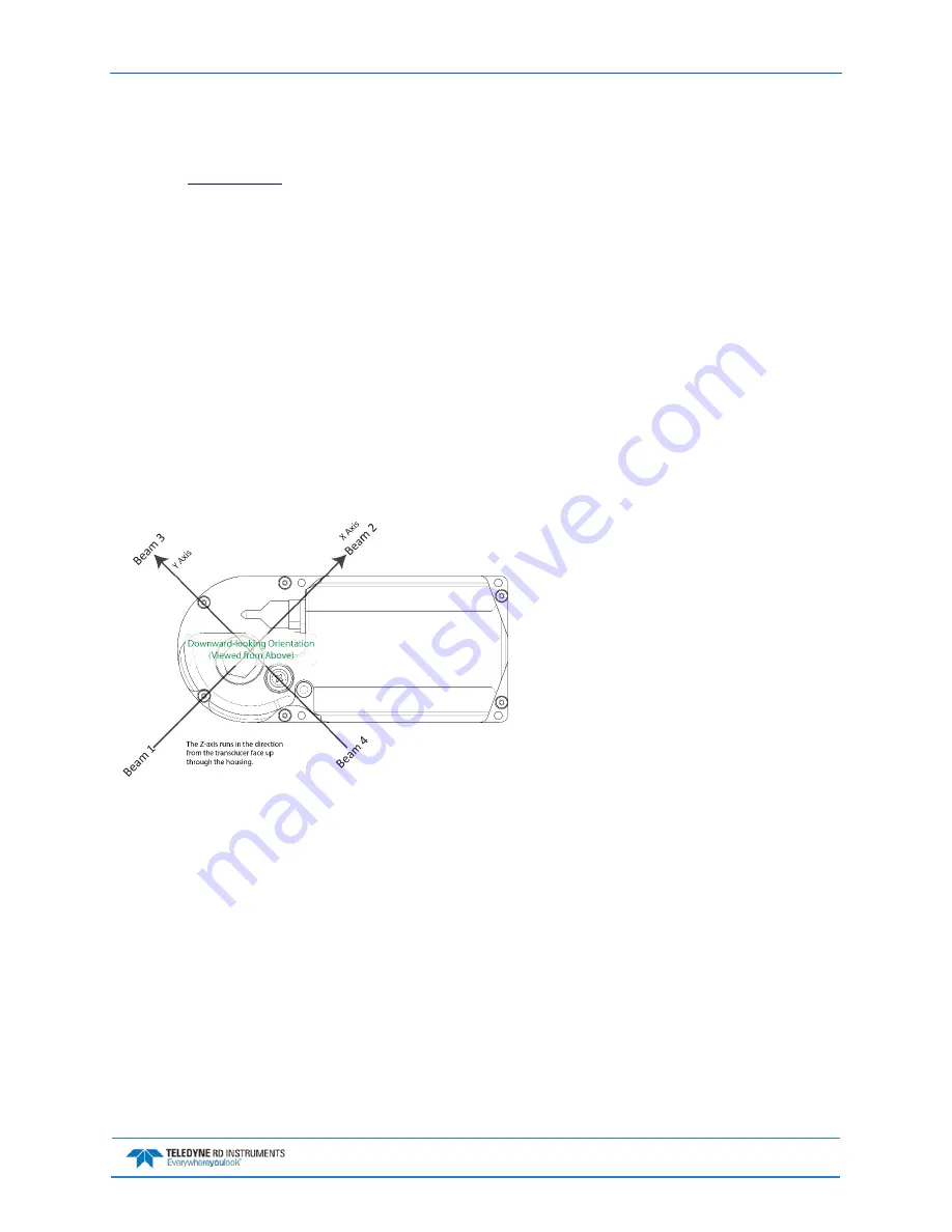
Instrument Coordinates
. (X, Y, Z) Instrument Coordinates are selected by the EX01xxx command. This set
of axes is always oriented the same relative to the transducer head. Looking at the end view of the hous-
ing, the transducers are labeled clockwise in the order 3-2-4-1 (Figure 17). When you look at the face of
the transducer head, the transducers are labeled clockwise in the order, 3-1-4-2 (see Figure 18, page 30).
The X-axis lies in the direction from transducer Beam 1 towards transducer Beam 2 and the Y-axis lies in
the direction from transducer Beam 4 towards transducer Beam 3. The Z-axis lies along the axes of sym-
metry of the four beams, pointing away from the water towards the housing.
Figure 17.
X, Y, and Z Velocities (ROV version
shown)
The PD0 Bottom Track output data format as-
sumes that the instrument is stationary and the
bottom is moving.
•
If Beam 3 is going forward, then the Y
velocity is negative.
•
If Beam 2 is going forward, then X ve-
locity is negative.
•
If the bottom is going towards the face
of a down facing DVL, then Z is positive.
The PD3 through PD6 data formats assume that
the bottom is stationary and that the DVL or
vessel is moving.
•
If Beam 3 is going forward, then the Y
velocity is positive.
•
If Beam 2 is going forward, then X ve-
locity is positive.
•
If the bottom is going towards the face
of a down facing DVL, then Z is nega-
tive.
Ship Coordinates (or Righted Instrument Coordinates)
. (S, F, M) Ship Coordinates are selected by the
EX10xxx command. TRDI uses the names Starboard, Forward, and Mast, although these axes are more
commonly called the roll, pitch, and yaw-axes, respectively. Assuming that Beam 3 is aligned with the keel
on the forward side of the DVL, for the downward-looking orientation, these axes are identical to the in-
strument axes:
S = X, F = Y, M = Z
For the upward-looking orientation, these axes are rotated 180° about the Y-axis:
S = -X, F = Y, M = -Z