


D-5
© Teledyne Limited
DPN 402197 Issue 7.1
It is important to be aware that changing the frequency will change the coil voltage results achieved.
The expected coil voltages for the available frequency outputs are explained in
.
D.3 Fault Identification
If the signal strength displayed on the Run Window does not show 1.0 to 1.5e6 at 25Hz for all channel
check the following:
❐
Check the condition of the battery in the coil tester. Press the power button and confirm a con-
stant green light. If a red or unlit LED is indicated, it is necessary to replace the battery.
❐
Check DeepView is showing the channel under test. Note that to display the port and star-
board fore-aft channels (PF and SF respectively) the Forward Search Window must be
selected.
❐
Check that the 350 system has been configured correctly with the coil calibration constants for
all six search coil channels. Check the values displayed in DeepView correspond to their
proper physical channels.
❐
Check the Spectrum Analyser to make certain that all six channels are receiving spurious sig-
nals from sources such as noise, mains frequency pickup, etc. If there are no received signals,
investigate a possible fault condition by referring to
D.4 Battery Replacement
The Coil Tester includes a battery condition LED. Press the battery test switch on the coil tester and
check the LED first shows orange and then, after a short delay, shows green. The LED should remain
green while the switch is pressed to indicate the battery is in good condition.
If the LED goes red or doesn’t illuminate, replace the battery.
To replace the battery complete the following steps:
1. Unscrew the battery compartment end cap.
2. Remove the battery from its positioned secure clip.
3. Replace with a new battery and connect the battery connector.
4. Screw the battery compartment door back into place.
5. Press and hold down the power battery switch on the coil tester and confirm that the battery
condition LED shows the battery to be in a good condition.
The battery life for continuous use is estimated to be thirteen hours or three years in stand-by mode.
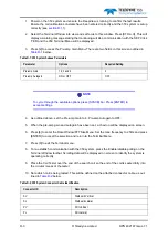
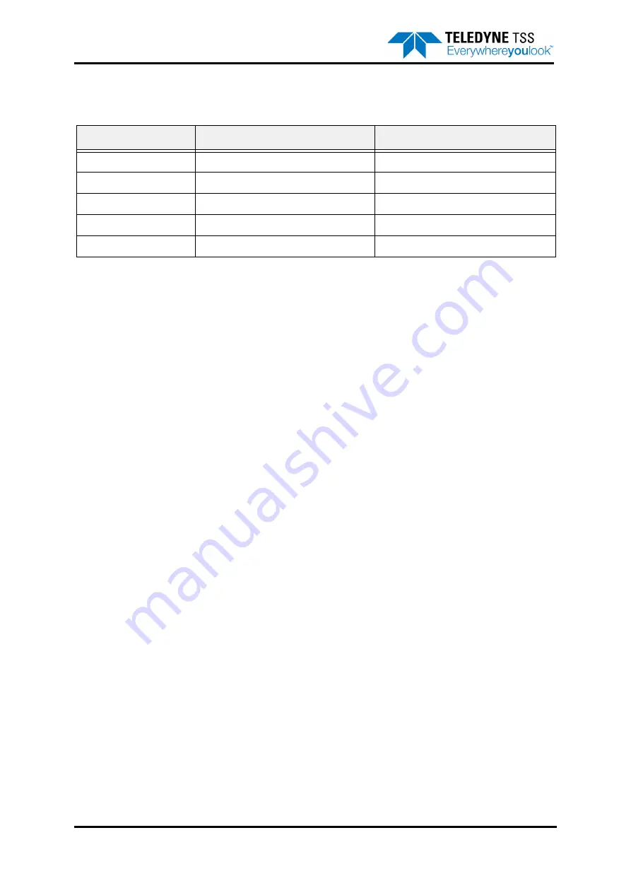
Table D-4: Coil Tester Frequency settings and expected coil voltages
Switch Position
Frequency Output
Coil Voltage
5
25Hz +/- 0.0025Hz
1.0 to 1.5e6
4
24Hz +/- 0.0025Hz
0.94 to 1.44e6
3
23Hz +/- 0.0025Hz
0.89 to 1.39e6
2
22Hz +/- 0.0025Hz
0.83 to 1.33e6
1
21Hz +/- 0.0025Hz
0.79 to 1.29e6