


DPN 402197 Issue 7.1
© Teledyne Limited
A- 2
A.3 Signal Isolation
Marine survey environments suffer from significant levels of background noise produced by other
electrical systems on board the ROV. The 350 systemmust remove this noise from the coil signals
before it can perform meaningful calculations.
The SEP samples the supplied signals approximately 1000 times per second and uses powerful signal
processing techniques to determine the spectrum of received frequencies.
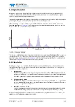
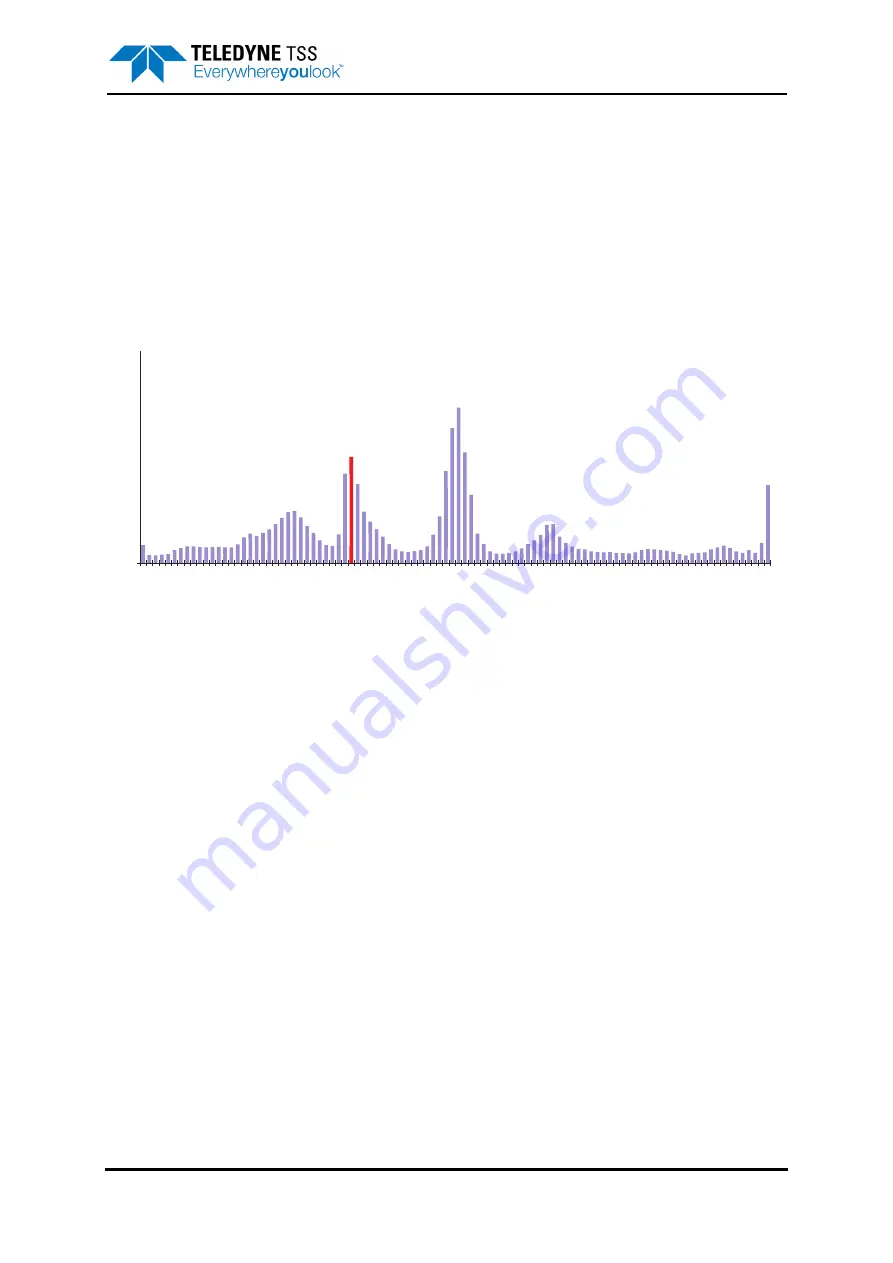
After processing the signals in this way, the SEP divides the entire received spectrum into narrow
‘windows’ as shown in
. The system stores the instantaneous signal amplitude for each of
these ‘windows’ in a series of memory locations.
Figure A-2: Frequency ‘windows’
This process isolates the various frequency components in a signal very effectively so that the system
can distinguish the tone frequency easily from among the background noise. DeepView provides a
Spectrum Analyser feature similar to
, with the tone frequency identified as a solid red bar.
The example in
shows the tone frequency at 33Hz.
A.4 Calculation
By using an array of two coil triads, the 350 System avoids potential sources of measurement error
caused by changes in the amplitude of the tone signal. Calculations performed by the 350 System
provide three modes of operation:
1.
Survey mode
:
The SDC displays the vertical range to target and the lateral offset of the target relative to the
centre of the coil array. If the System receives altitude information or you have specified a fixed
coil height, this mode can also supply measurements of altitude and target depth of cover.
2.
Forward Search mode
:
The SDC can display an
estimate
of the range to a tone-carrying cable that lies along an inter-
secting course ahead of the ROV. This facility allows you to use the 350 System to conduct a
search for a target in the survey area.
3.
Skew Measurement mode
:
The SDC displays and transmits the angle of skew measured between the track of the target
and the ROV heading. Ideally, there should be no angle of skew present during a survey.
DeepView displays all measurements relative to the ROV. They might therefore contain errors if you
operate the ROV with some angle of roll or pitch.
0
10
20
100
Frequency (Hz)
90
80
70
60
50
40
30
Relative amplitude
Relative amplitude