Teledyne GMI PS200 Скачать руководство пользователя страница 32

PS200

PORTABLE GAS MONITOR

26

64171

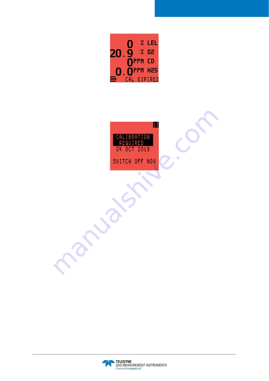
Figure 39:  CAL EXPIRED

If calibration is overdue, a configurable option only allows the user to switch the monitor off, as

shown in 

Figure 40:


Calibration Required

.

Refer to 

Section 9. Calibration

 for calibration options.

Figure 40:  Calibration Required

Revision 12

.1

Содержание GMI PS200

Страница 1: ...User Guide User Manual 64171 Revision 12 1 PS200 PORTABLE GAS MONITOR ...

Страница 2: ...Manual but the Company does not accept any responsibility for errors or omissions and their consequences Information in this user guide is subject to change without notice This User Manual does not constitute a specification or basis for a contract MODIFICATION NOTICES The Company aims to notify customers of relevant changes in the product operation and maintain this user guide up to date Due to c...

Страница 3: ...y affect sensor readings This includes changes in pressure humidity and temperature Note that both pressure and humidity changes can also affect the amount of oxygen present in the atmosphere Do not use the monitor in potentially hazardous atmospheres containing greater than 21 oxygen SPECIAL CONDITIONS OF USE The monitor is designed for use in harsh environments The monitor is sealed to IP67 and ...

Страница 4: ... the Monitor On 10 3 3 1 Monitor Identification 1 1 3 3 2 User Name Number Only Option 1 1 3 3 3 Date and Time 1 1 3 3 4 Bump Due Date Option 12 3 3 5 Calibration Due Date 13 3 3 6 Service Due Date Option 13 3 3 7 Select Calibration Gas Option 13 3 3 8 Sensor Confirmation Check 14 3 3 9 Normal Operating Display 14 3 4 Switch the Display Backlight On Off 15 3 5 View MAX MIN STEL LTEL 15 3 6 Manual ...

Страница 5: ...y Fault 25 5 6 Calibration Required 25 6 Manual Bump Test Options 27 6 1 Bump Testing 27 6 2 Initiating a Manual Bump Test 27 6 2 1 Pumped Instruments Regulator Selection 28 6 3 Applying Test Gas 28 6 4 Quick Full Bump Test 29 6 4 1 Quick Bump Test 29 6 4 2 Full Bump Test 29 6 5 Confirm Alarms 29 6 5 1 Bump Test Pass 29 6 5 2 Bump Test Fail 30 7 Recharging the Batteries 31 7 1 General 31 7 2 Recha...

Страница 6: ...RTABLE GAS MONITOR vi 64171 9 3 Calibration Validity 38 10 Accessories 39 A Operating Parameters Sensor Types 40 A 1 Typical Operating Parameters 40 A 2 LEL Sensor Types 42 B Technical Support 43 Revision 12 1 ...

Страница 7: ...entions The following visual elements are used throughout this guide where applicable WARNING READ UNDERSTAND AND FOLLOW THE ENTIRE CONTENT OF THIS GUIDE PRIOR TO USE FAILURE TO DO SO MAY RESULT IN SERIOUS INJURY OR DEATH Icon Description WARNING THIS ICON AND TEXT INDICATE A POTENTIALLY HAZARDOUS SITUATION WHICH IF NOT AVOIDED COULD RESULT IN DEATH OR INJURY Caution This icon and text indicate an...

Страница 8: ...lass I Div 1 Groups A B C and D T4 Class I Zone 1 AEx ia d IIC T4 Gb Ex ia d IIC T4 Gb or Class I Div 1 Groups C and D T4 Class I Zone 0 AEx ia IIB T4 Ga Ex ia IIB T4 Ga when fitted with the SGX VQ548MP sensor Non combustible Instruments Class I Div 1 Groups A B C and D T4 Class I Zone 0 AEx ia IIC T4 Ga Ex ia IIC T4 Ga MED Marine Equipment Directive A 1 3 30 Module B E European Mark of Conformity...

Страница 9: ... S12 13 01 2000 Combustible C22 2 No 152 M1984 Combustible excludes IR sensor option 2yr O2 sensor only 1 3 General Safety Information WARNING ALL INDIVIDUALS WHO HAVE OR WILL HAVE RESPONSIBILITY FOR USING OR TESTING THIS PRODUCT MUST READ AND UNDERSTAND THE CONTENTS OF THIS MANUAL THE PRODUCT WILL PERFORM AS DESIGNED ONLY IF USED AND TESTED IN ACCORDANCE WITH THE MANUFACTURER S INSTRUCTIONS FAILU...

Страница 10: ...r consequential damage to any third party against the Company is removed if the above warnings are not observed 1 4 Additional Safety Details CSA ONLY Caution Before each days usage test on a known concentration of methane equivalent to 25 50 of full scale concentration accuracy must be within 0 to 20 of actual Accuracy may be corrected by calibration refer to zX Refs online Section 9 Calibration ...

Страница 11: ...duit Caution Do not charge in a hazardous area Um 6V Mise en garde Ne pas charger en zone dangereuse Um 6V Note CSA have only assessed the LEL combustible gas detection portion of this monitor for performance Remarque CSA a seulement évalué la partie LIE pour la mesure des performances en détection de gaz inflammables Revision 12 1 ...

Страница 12: ... threshold limits or if the monitor develops a fault users will be alerted by audible visible and vibratory alarms The monitor is available as either a pumped or diffusion model and is powered by a fast charging internal Li ion lithium ion battery The monitor is simple to use and is operated via two buttons refer to Figure 2 PS200 Portable Gas Detector Figure 2 PS200 Portable Gas Detector The moni...

Страница 13: ... display OK as illustrated in Figure 5 OK Display Example 4 Gas Figure 5 OK Display Example 4 Gas NOTE Character size increases if fewer sensors are configured as illustrated in Figure 4 Display Examples NOTE This manual describes the operation of a default 4 gas monitor Configurable options are available and are detailed in italic text where applicable Revision 12 1 ...

Страница 14: ...sories Quick Configuration Display allows the configuration to be viewed without fully switching the monitor ON Typical operating parameters are detailed in Appendix A Operating Parameters Sensor Types of this manual 2 3 Datalogging Datalogging allows gas measurements event logs bump tests and calibration details to be stored for downloading to a PC Laptop via a USB connection Typically the monito...

Страница 15: ... monitor is within the calibration period The oxygen sensor if installed operates correctly The sensor responds to the user breathing on the front of the monitor by displaying a value below 20 9 Caution The monitor can be supplied with a flammable gas sensor This sensor is designed for use in concentrations of gas not exceeding the Lower Explosive Limit LEL Exposing the sensor to concentrations of...

Страница 16: ... will display sensors fitted calibration due date pumped or diffusion LEL calibration gas Figure 7 Quick Configuration Display 3 3 Switching the Monitor On Press and hold the R button for one second to switch the monitor ON refer to Figure 6 Function Buttons The flash screen appears as shown in Figure 8 Flash Screen and the monitor begins its warm up routine A countdown timer appears in the top ri...

Страница 17: ...tion Display Figure 9 Monitor Identification Display 3 3 2 User Name Number Only Option This configurable option disabled by default allows the user to select a name or identification code as illustrated in Figure 10 User Name The monitor will include this name or code with all Bump Calibration and Event logs Figure 10 User Name 3 3 3 Date and Time The monitor s date and time are displayed as illu...

Страница 18: ...s overdue then pause awaiting user acceptance Figure 13 Bump Overdue force the user to switch monitor OFF when overdue This feature also comes with a factory set option to display the number of days remaining until the next bump is due Figure 12 Bump Due Date Figure 13 Bump Overdue To continue press the R button once to acknowledge bump test is overdue To abort warm up and automatically switch the...

Страница 19: ... due indicate that service is overdue then pause awaiting user acceptance force the user to switch the monitor OFF when service is overdue Options also exist for displaying the service due date including displaying the number of days remaining In all instances if enabled the monitor only displays the message within 90 days of service due date The service due date is illustrated in Figure 15 Servic...

Страница 20: ...ars next to each sensor type to confirm that the sensor has been zeroed correctly as shown in Figure 17 Sensor Check Displays If a wrench symbol is displayed refer to Section 5 3 Zero Fault and Section 5 4 Sensor Faults Figure 17 Sensor Check Displays 3 3 9 Normal Operating Display When warm up is completed successfully the backlight switches off and the normal operating screen is displayed as ill...

Страница 21: ...ates the short term exposure STEL and long term exposure LTEL for CO and H2S To view MAX MIN STEL LTEL 1 From the normal operating display press the R button once to switch the monitor backlight ON 2 While the backlight is still ON press the R button once to view the MAX gas values 3 Press the R button a 2nd time to view the MIN gas values 4 Press the R button a 3rd time to display the STEL values...

Страница 22: ...ividually programmable to be either Latching alarms are active until the user resets by pressing and holding the R button after the gas readings have returned to a safe level Non Latching alarms will reset automatically when the gas readings have returned to a safe level The audible alarm on each pre set alarm can be muted for 60 seconds by pressing and holding the R button After this time should ...

Страница 23: ...mple Line Connection 3 8 1 Pump Operation Press and hold the R button to start or stop the pump When the pump is running a pump symbol as highlighted in Figure 22 Pump Symbol rotates in the display Figure 22 Pump Symbol NOTE The operation of the confidence beep and or LEDs is configurable NOTE It is only possible to switch the pump ON OFF when monitor alarms are inactive NOTE Pump cannot be switch...

Страница 24: ...is displayed as illustrated in Figure 23 Self Test The current username if configured will appear at the top of the display Figure 23 Self Test 3 10 Switch the Monitor OFF Press and hold both the L and R buttons to switch the monitor OFF The monitor display starts a countdown from 3 to OFF as shown in Figure 24 Switch OFF Figure 24 Switch OFF The audible alarm sounds every second to alert user tha...

Страница 25: ...The monitor calculates the Short Term Exposure Limit STEL and Long Term Exposure Limit LTEL known as Time Weighted Average TWA readings for each toxic gas range Each toxic range has STEL and LTEL alarms in addition to HI and HIHI alarms In the following examples Figure 25 O2 LOLO Alarm shows a LOLO Oxygen alarm and Figure 26 LEL HIHI Alarm shows a HIHI LEL alarm Figure 25 O2 LOLO Alarm NOTE A TWA ...

Страница 26: ...Latching alarm silences the audible alarm for a period of 60 seconds If the gas reading during that time falls below the alarm set point the user must acknowledge the visual alarm to clear it 4 4 High Flammable Gas Over range Alarm An over range alarm protects the user and the LEL sensor during exposures to high concentrations of flammable gas If the LEL reading exceeds 100 LEL see 4 4 1 10 Second...

Страница 27: ...itch OFF by pressing and holding both L and R buttons A timer counts down from 10 seconds to 0 and the message GET OUT alternates with HIGH GAS as shown in Figure 28 GET OUT HIGH GAS Timer Figure 28 GET OUT HIGH GAS Timer NOTE To avoid accidental switch off in this dangerous state the off cycle is increased to 10 seconds Revision 12 1 ...

Страница 28: ...llustrated in Figure 30 BAT FAULT Warning The display turns red the audible alarm sounds continuously and the red LED s remain on After 3 minutes the monitor automatically switches OFF Figure 30 BAT FAULT Warning 5 3 Zero Fault 5 3 1 Zero Fault At The End Of Warm up If the monitor is switched on in gas and a sensor fails to zero correctly the display turns red and the audible visual alarms activat...

Страница 29: ...r to an approved service repair facility A configurable option only allows the user to switch the monitor OFF if a ZERO FAULT is detected as shown in Figure 33 ZERO FAULT Switch OFF Figure 33 ZERO FAULT Switch OFF 5 3 2 Zero Fault During Operation If ZERO FAULT is displayed during instrument operation then Leave the monitor ON for 30 60 minutes Switch OFF then ON If ZERO FAULT persists recalibrate...

Страница 30: ...Fault CO or H2S If a sensor fault is detected for CO or H2S as illustrated in Figure 35 CO H2S SENSOR FAULT allow the monitor to run in clean air for 20 minutes If the fault persists return the monitor to an approved service repair facility Figure 35 CO H2S SENSOR FAULT 5 4 3 Flow Fault Pumped Monitors Only If a sample fault exists the monitor displays a FLOW FAULT warning as shown in Figure 36 FL...

Страница 31: ...bration CALIBRATION OVERDUE appears during warm up as shown in Figure 38 Calibration Overdue The monitor will still operate but sensor response may have diminished The monitor should be recalibrated Press the L button once to abort the warm up sequence and automatically switch OFF the monitor Figure 38 Calibration Overdue Alternately press the R button once to acknowledge the warning cancel the au...

Страница 32: ...AL EXPIRED If calibration is overdue a configurable option only allows the user to switch the monitor off as shown in Figure 40 Calibration Required Refer to Section 9 Calibration for calibration options Figure 40 Calibration Required Revision 12 1 ...

Страница 33: ...n tubing 6 2 Initiating a Manual Bump Test If enabled switch the monitor ON by pressing the L button During warm up the BUMP TEST confirmation screen appears as shown in Figure 41 BUMP TEST Confirmation Screen Press the R button to continue Figure 41 BUMP TEST Confirmation Screen When warm up is complete the APPLY GAS screen appears as shown in Figure 42 Apply Gas Screen 4 Gas Model WARNING A QUIC...

Страница 34: ...d during the bump test as illustrated in Figure 43 Regulator Valve Choice YES use a demand or balanced flow regulator press the R button NO use a direct flow regulator press the L button Figure 43 Regulator Valve Choice 6 3 Applying Test Gas Apply the test gas to the monitor via the direct flow regulator set to 0 5 l min as shown in Figure 44 Bump Test Kit Figure 44 Bump Test Kit Revision 12 1 ...

Страница 35: ...ill activate and a symbol will appear if the readings are within these limits otherwise a symbol will be displayed 6 5 Confirm Alarms The user is prompted to confirm if the audible and visual alarms were activated as shown in Figure 45 Confirm Alarms Figure 45 Confirm Alarms 6 5 1 Bump Test Pass After selecting YES BUMP TEST PASS is displayed as shown in Figure 46 Bump Test Pass The bump test resu...

Страница 36: ...s shown in Figure 47 Confirm Alarms Fail Figure 47 Confirm Alarms Fail After selecting YES or NO BUMP TEST FAIL is displayed and the user is instructed to switch the monitor off as shown in Figure 48 Bump Test Fail Switch Monitor OFF Figure 48 Bump Test Fail Switch Monitor OFF If a monitor fails a bump test then a full re calibration is necessary Revision 12 1 ...

Страница 37: ...Ensure the locating tongue on the clip engages with the monitor locating slot and is firmly seated refer to Figure 49 Charging Comms Clip Connection Figure 49 Charging Comms Clip Connection 2 Connect the supplied MINI USB to USB Cable to the Charging Comms Clip as shown in Figure 50 Connect Cable to Charging Comms Clip WARNING NEVER ATTEMPT TO RECHARGE THE BATTERIES IN A HAZARDOUS AREA Caution Swi...

Страница 38: ...1 Connecting the Cable to the USB Power Adapter 4 During charging the battery symbol and CHARGING flash in the display 5 When charging is complete the full battery symbol and CHARGED are displayed 6 Disconnect from the power source 7 Grip the charging comms clip and firmly pull it away from the monitor Note Leaving the monitor connected to the charger will not damage it Revision 12 1 ...

Страница 39: ...ters periodically for contamination or damage 8 2 1 Replacing the Hydrophobic Water Filter Figure 52 Hydrophobic Filter Replacement 1 Using a No 1 Pozidriv screwdriver unscrew the captive screw 2 Slide the filter cover away from the display until the locating lugs disengage from the locating slots 3 Lift the cover away from the monitor 4 Remove the hydrophobic filter 5 Insert a new hydrophobic fil...

Страница 40: ... rear of the inlet nozzle 3 Push a matchstick or similar into the front of the inlet nozzle and remove the sample inlet filter from the rear of the inlet nozzle 4 Insert a new sample inlet filter into the rear of the inlet nozzle Ensure the rough surface faces the inlet filter sample side 5 Fit the inlet nozzle The inlet nozzle will only fit in one direction 6 Using a No 1 Pozidriv screwdriver ins...

Страница 41: ... 4 Automatic Calibration the GMI Automatic Bump Calibration Station shown in Figure 54 PS200 Auto Bump Calibration Station provides controlled delivery of gases permitting users to bump test and calibrate the monitor in a controlled manner whilst maintaining a record of calibration results For further details contact GMI or an authorized distributor Figure 54 PS200 Auto Bump Calibration Station WA...

Страница 42: ...f test 2 Continue holding the button until the self test finishes and the LCD displays ZERO CALIBRATION as shown in Figure 55 ZERO CALIBRATION Screen Figure 55 ZERO CALIBRATION Screen 3 Next in a clean air environment press and hold the R button to zero calibrate the monitor ranges Once the zero calibration finishes the monitor displays SPAN CALIBRATION as shown in Figure 56 SPAN CALIBRATION Scree...

Страница 43: ...ce calibration is successfully completed the user has the option of saving the results refer to Figure 59 CAL COMPLETE SAVE RESULTS Screen Figure 59 CAL COMPLETE SAVE RESULTS Screen 8 Using the L button highlight one of the 3 the available options A UPDATE saves the calibration data in the memory and automatically updates the calibration due date based on the option stored in the monitor set up me...

Страница 44: ...he user Individual codes of practice may dictate calibration intervals Regular calibration establishes a pattern of reliability and enables the calibration check period to be modified in line with operational experience As a guide the higher the risk the more frequently calibration should be checked Revision 12 1 ...

Страница 45: ...12 Sample Line Extender 66485 In Line Hydrophobic Filter Assembly 66545 Ball Float 64151 PS200 Confined Space Probe 64100 Carrying Case 64150 PS200 Confined Space Demonstration Kit 64160 PS200 Field Kit Part Number Description 64138 5 Way Charger 64248 In Vehicle Charging Adapter 12V 24V USB 64491 In Vehicle Charging Cradle Part Number Description 64051 Manual Bump Kit c w Combi Test Gas 99146 Dir...

Страница 46: ...t Operating Temperature Lim its 4ºF to 122ºF 20ºC to 50ºC Storage Temperature Limits 40ºF to 149ºF 40ºC to 65ºC Humidity 0 to 95 R H non condensing Nominal Flow Rate 0 132 to 0 185 gals min 0 5 to 0 7 liters min Max 97 ft 30 m sample line Typical Flow Fail Rate 0 026 to 0 053 gals min 0 1 to 0 2 liters min Warm up Stabilization Time 30 seconds 90 seconds for monitors with IR flammable sensor optio...

Страница 47: ...sical impact testing to EN 60079 section 1 5 IP Rating IP67 Datalogging Timed Minimum of 6 months datalogging Session Minimum of 360 logs Calibration Minimum of 8 logs Bump Minimum of 360 logs Based on 1 gas event every 1 hour during a typical 8 hour shift with a datalogging interval of 1 minute Revision 12 1 ...

Страница 48: ...2 Enhanced Filtered P N 64825 Enhanced H2S Silicone poisoning resistance C1 C6 Hydrocarbons Includes but not limited to Methane Ethane Propane Butane Pentane Hexane Hydrogen IIC A B C D Class I Div 1 2 Zones 1 2 Low Power P N 66750 Improved battery life C1 C5 Hydrocarbons Includes but not limited to Methane Ethane Propane Butane Pentane IIB C D Class I Div 1 2 Zones 0 1 2 Infrared P N 66761 Improv...

Страница 49: ...ble trouble free service Contact your regional technical support if you have technical questions need support or if you need to return a product Details can be found at www teledynegasandflamedetection com Note When returning a product contact Technical Support to obtain a Return MaterialAuthorization RMA number prior to shipping ...

Страница 50: ... 713 559 9200 Inchinnan Business Park Renfrew PA4 9RG Scotland UK Tel 44 0 141 812 321 1 290 Guigiao Road Pudang Shanghai 201206 People s Republic of China Tel 86 21 3127 6373 www teledynegasandflamedetection com 64171 Revision 12 1 Copyright 2020 Teledyne Gas and Flame Detection All rights reserved ...

Отзывы: