background image

2101 Field Wizard
Section 3  Operation

3-4

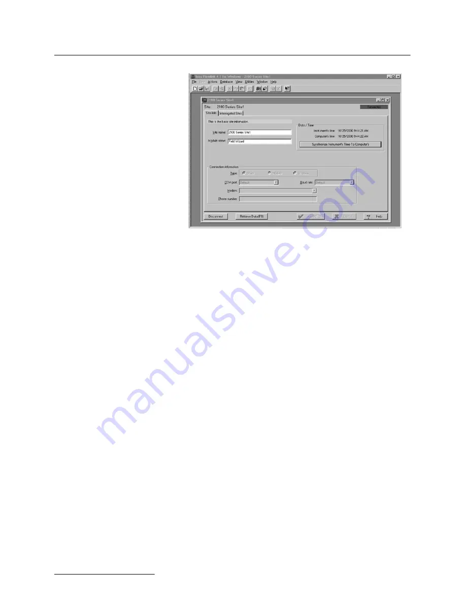
Figure 3-2 Flowlink Site Info Screen

Complete the following steps:

1. Click the 

Synchronize Instrument’s Time to Com-

puter’s

 button to synchronize the Field Wizard’s time to 

that of your PC. (If you are using multiple PCs, select just 
one PC to synchronize with.) You will be notified that this 
operation will set the time of the Field Wizard to match 
that of the PC. Click OK.

2. The Field Wizard is shipped with default site and module 

names. Use the 

Site Name

 and 

Module Name

 fields if 

you want to provide more descriptive names. Select 

Apply 

(F9)

 to write that information to the instrument.

3. Click 

Retrieve Data (F8)

 to retrieve the data from the 

Field Wizard. For synchronization purposes, this should be 
done even if this is the first time you are connecting the 
Field Wizard to the PC. The process transfers a file con-
taining site interrogation times from Flowlink to the Field 
Wizard. With this information, the Field Wizard will know 
when data was last retrieved from your site(s). When 
brought to a site, the Field Wizard will retrieve only the 
necessary data.

The process will take some time. A gauge will be displayed
so you can monitor the progress. If needed, click Cancel to
cancel the data transfer. The data will be retained in the
Field Wizard.

Data that has been retrieved by the PC will remain in the
Field Wizard until it is connected to a site and begins col-
lecting new data. This allows you to copy data to multiple
PCs.

4. Select 

Disconnect

 to end your PC session and disconnect 

the Field Wizard.

Содержание Field Wizard 2101

Страница 1: ...2101 Field Wizard Installation and Operation Guide Part 60 2003 155 of Assembly 60 2004 070 Copyright 2002 All rights reserved Teledyne Isco Inc Revision K March 25 2007 ...

Страница 2: ......

Страница 3: ...Return Authorization Number specified Be sure to include a note describing the malfunction This will aid in the prompt repair and return of the equipment Teledyne Isco welcomes suggestions that would improve the information presented in this manual or enhance the operation of the equipment itself Teledyne Isco is continually improving its products and reserves the right to change product specifica...

Страница 4: ......

Страница 5: ...Keypad 3 1 3 3 Flowlink Connection 3 3 3 3 1 Connecting To a PC 3 3 3 3 2 Communication Resolution 3 5 3 3 3 Site and Module Name 3 5 3 4 Connecting to a Site 3 6 3 5 Site Time Synchronization 3 7 3 6 Data Retrieval Mode 3 7 3 6 1 Retrieve Data Display 3 9 3 6 2 Data Retrieval Log Display 3 11 3 6 3 Site Setup Display 3 12 3 6 4 Data Display 3 15 3 6 5 Site Information Display 3 16 3 7 Standalone ...

Страница 6: ... Connecting the Communication Cable to the Field Wizard 2 3 2 3 Flowlink Site Info Screen 2 4 2 4 Data Retrieval Mode Main Display 2 10 3 1 Field Wizard Keypad and Display 3 2 3 2 Flowlink Site Info Screen 3 4 3 3 Field Wizard Connected to a 2150 Site 3 6 3 4 Synchronize Time Display 3 7 3 5 Data Retrieval Mode Main Display 3 8 3 6 Retrieve Data Display 3 9 3 7 Data Retrieval Status Display 3 9 3 ...

Страница 7: ...w 1 3 1 2 Field Wizard Components Bottom View 1 4 1 3 2101 Field Wizard Technical Specifications 1 5 1 4 Field Wizard Connector Pins 1 5 4 1 Modbus ASCII Address 1 Register Definitions 4 6 4 2 Modbus ASCII Address 2 N 1 Register Definitions 4 7 4 3 Measurement Parameters by Model Number 4 9 ...

Страница 8: ...2101 Field Wizard Table of Contents vi ...

Страница 9: ...0 Series module using the same locking mechanism that connects the 2100 Series modules to each other Because modules have unique assigned names the Field Wizard can retrieve data from multiple modules and can be easily moved from site to site The Field Wizard uses flash memory which retains data without the concern of power failures or aging backup batteries The data storage memory can hold up to ...

Страница 10: ...depend upon what operation you are performing and will be shown in the display window The four arrow keys are used for navigation within menus and displays The Enter key is used to complete data entry acknowledge prompts and signal the start of certain operations Numeric keys are active when numeric data is to be entered Press the Help key to obtain context sensitive help The Power key places the ...

Страница 11: ...omponents Side View Item No Name Description 1 Communication Connector This port is used to connect to a personal computer running Flowlink software 2 Connector Cap Insert into the communication connector when it is not in use to protect the connector from damage 3 Latch Release Push in to unlock the module from a stack ...

Страница 12: ...Series module and is used to transfer data 2 Connector Cap Insert into the communication connector when not in use to protect the connector from moisture damage When the connector is in use store the connector cap in the cap holder 3 Cap Holder Stores the connector cap when the communication connector is in use 4 Desiccant Cartridge and Hydrophobic Filter Prevents moisture from entering the unit 5...

Страница 13: ... to 140 F 40 to 60 C Setup and Data Retrieval Serial connection to IBM PC or compatible computer with Isco Flowlink soft ware version 4 12 or higher Baud Rate 38 400 File System Memory Capacity The Field Wizard is capable of storing a minimum of 1 5 Mbytes of data A B C D E F G Table 1 4 Field Wizard Connector Pins Pin Name Description A LONA Neuron differential transceiver Data A B LONB Neuron di...

Страница 14: ... 1 5 Technical Service Although Teledyne Isco designs reliability into all of its equipment there is always the possibility of a malfunction occurring You can use this manual to help in diagnosing and repairing any malfunctions If the malfunction persists call or write the Teledyne Isco Technical Service Department for assis tance Teledyne Isco Inc Technical Service Department P O Box 82531 Lincol...

Страница 15: ...cking list If any parts are missing contact the delivery company and Teledyne Isco s Customer Service Department When you report missing part s please indicate them by part number In addition to the main packing list there may be other packing lists for various sub components It is recommended that you retain the shipping cartons as they can be used to ship the unit in the event that it is necessa...

Страница 16: ...nd storage tanks These spaces may become hazardous environments that can prove fatal for those unpre pared These spaces are governed by OSHA 1910 146 and require a permit before entering 2 3 Connecting To Flowlink Before you use your Field Wizard in the field to collect data you need to synchronize it to Isco s Flowlink software on a personal computer PC Use the following instructions to connect t...

Страница 17: ...zard Uncap the communication connector on the right side of the Field Wizard and attach the Communications Cable as shown in Figure 2 2 Connect the other end of the Communications Cable to a serial COM port on the PC As a default Flowlink setting the Quick Connect dialog box opens when you start Flowlink If it is not open click the Quick Connect icon or select File Quick Connect ...

Страница 18: ...es Select Apply F9 to write that information to the instrument 3 Although data has not yet been collected you need to click Retrieve Data F8 This transfers a file containing site interrogation times from Flowlink to the Field Wizard With this information the Field Wizard will know when data was last retrieved from your site s When brought to a site the Field Wizard will then retrieve only the nece...

Страница 19: ...ing too much force Never press on both sides at the same time Do not force the latch if it is obstructed While some degree of pressure must be applied to slide the latch the ends of the latches should never bend more than 1 8 L attache peut être endommagée en la forçant Ne jamais presser simultanément des deux côtés à la fois Ne pas forcer en cas de résistance Ne jamais tordre les extrémités des a...

Страница 20: ...ocking the latch Locate the latch release on the right side of the module Push in to slide the latch toward the left of the module Push Figure 2 2 Locking the latch Locate the latch extending from the left side of the module Push in to slide the latch toward the right of the module ...

Страница 21: ... cation connector will be sealed by its mating connector CAUTION Caps PUSH ON and PULL OFF Do not rotate the caps to remove them from the connectors Capuchons POUSSER et TIRER Ne pas tourner les capuchons pour les enlever des prises Note For modules to correctly stack and lock together protective caps between the modules must be stored on the holders 2 4 3 Stacking Modules To stack a Field Wizard ...

Страница 22: ...2 8 Figure 2 7 Field Wizard module unlock the latch Unlock the latch to release the lower cap Figure 2 8 Field Wizard module uncap the connector Pull the cap off of the connector Figure 2 9 Field Wizard module push cap into holder Push the cap into the holder ...

Страница 23: ... Uncap the connector on the top 2100 Series module Store the cap on the holder Figure 2 11 Align the modules Align the modules and gently press the Field Wizard Module onto the 2100 Series Module Figure 2 12 Push down and lock the latch While gently pressing down on the stack lock the Field Wizard Module s latch ...

Страница 24: ...ep and then see the display PLEASE WAIT as the unit queries the site for configuration information When it has obtained that information it will format it into a display similar to that in Figure 2 18 Figure 2 4 Data Retrieval Mode Main Display More details about operating the Field Wizard at a site can be found in Section 3 4 ...

Страница 25: ...ion 1 06 or greater Flowlink Help Detailed Flowlink instructions are beyond the scope of this manual Flowlink s operating instructions are available in a Windows Help format You can access the help topics for an active window by clicking on its Help button or by pressing F1 on your computer s keyboard You can also access Help topics by selecting Help from the Flowlink menu 3 2 Field Wizard Keypad ...

Страница 26: ... data is to be entered The key with a question mark on it is the Help key Press it to obtain context sensitive help while using the Field Wizard When you are in Help mode use the directional arrow keys to scroll through the information displayed Press the Help key again to exit the Help mode The Power key places the unit into an ultra low power state during which the display window will be blank T...

Страница 27: ...using the Field Wizard to transfer data to multiple computers you should designate one computer as the master and connect the Field Wizard to it first This will avoid problems with synchronizing the date and time 3 3 1 Connecting To a PC To connect the Field Wizard to a PC you will need Isco s commu nication cable P N 60 2004 046 and AC Adapter P N 60 2004 057 One end of the AC adapter plugs into ...

Страница 28: ...ata from the Field Wizard For synchronization purposes this should be done even if this is the first time you are connecting the Field Wizard to the PC The process transfers a file con taining site interrogation times from Flowlink to the Field Wizard With this information the Field Wizard will know when data was last retrieved from your site s When brought to a site the Field Wizard will retrieve...

Страница 29: ...the sites and modules that should be reconfigured and click the OK button Be aware that reconfiguring a module removes the Site Name Module Name program settings and any stored data The module is then restarted with the stable Site s Name a default Module Name and default program settings and the data storage is ready to accept new data 3 3 3 Site and Module Name The Field Wizard is shipped with a...

Страница 30: ...ay contain multiple 2100 Series Modules 1 On the top 2100 Series Module remove the connector cap from the communication connector and store the cap in its holder 2 Unlock the Field Wizard s latch by pressing in on the latch release right side 3 Underneath the Field Wizard module remove the cap from the communication connector and store the cap in its holder 4 Lock the Field Wizard s latch by press...

Страница 31: ...igure 3 4 Synchronize Time Display Press F1 SYNC to synchronize the site s time with that of the Field Wizard and the Master Computer The time will be syn chronized and you will be advanced to the Data Retrieval Mode Main Display Fig 3 5 If you do not want to synchronize the time press F6 CANCEL to advance to the Data Retrieval Mode Main Display Fig 3 5 3 6 Data Retrieval Mode The Field Wizard wil...

Страница 32: ...splayed at one time scroll arrows will appear on the right side of the screen Pressing the Up and Down arrow keys will scroll through the complete information for that module Press F6 NEXT to display data for the next module if there are two or more 2100 Series modules The actions assigned to the function keys are summarized below More complete descriptions are provided in the subsections that fol...

Страница 33: ...n will start if you select this option During data collection the name of the module being interro gated will be displayed along with a gauge so you can note the progress see Figure 3 7 If there is more than one module active at the site then the data will be retrieved one module at a time One module will be com pletely interrogated before data will be retrieved from any other module Figure 3 7 Da...

Страница 34: ...el your entry and return to the previous screen press F6 CANCEL The system will take the current date and retrieve data starting at midnight including the current day which is counted as day zero For example if the current date was March 11 and you requested to retrieve data for the past 7 days data retrieval would start at the beginning of March 4 and would include data through March 11 As anothe...

Страница 35: ... s han dling state is listed under the Saved header When data is first collected it will have a state of No After the data has been transferred to the Master Database on the PC the state will change to Yes Once you have transferred a site s data to the Master Database in Flowlink it is eligible to be purged thus freeing up memory space to collect more data Note however that site data with a handli...

Страница 36: ...articular site To exit the display and return to the Log Display press F6 EXIT 3 6 3 Site Setup Display The Site Setup displays shown in Figures 3 11 and 3 13 are accessed by pressing F3 SETUP from the Main Display One of the Setup displays is for the Field Wizard the other is for 2100 Series modules in the site s stack Press F2 NEXT to move between modules An indicator X of X after the module nam...

Страница 37: ...eval Mode Main Display Press F4 SELECT to change the backlight mode for the Field Wizard The following screen will be displayed Figure 3 12 Field Wizard Backlight Mode Settings There are three options for the backlight mode on the Field Wizard Highlight the desired option and press F1 APPLY to select that option Press F6 CANCEL to return to the Field Wizard Site Setup display ALWAYS OFF The backli...

Страница 38: ...e Field Wizard Before you can calibrate one valid reading must have been taken so there is a value to calibrate to On the Site Setup display use F2 NEXT to display the module you want to calibrate then press F3 CALIB The Level Cali bration window for the selected module will appear Figure 3 14 Figure 3 14 Level Calibration Display The level currently being detected will be displayed To change the ...

Страница 39: ... through the information Once you have viewed the information press F6 EXIT to exit to the Site Setup display 3 6 4 Data Display When you press F4 DATA from the Main Display the Data screen shown in Figure 3 16 will appear Figure 3 16 Data Display This display shows information about the data stored inside the currently selected module the time and date of the most recent reading total number of r...

Страница 40: ...rs Use the Up and Down arrow keys to scroll between the different modules To identify a module highlight it using the arrow keys and then press F5 IDENTIFY This will cause the LED for that module to light up continuously for a short period of time If you press F5 IDENTIFY when Field Wizard is highlighted the system beeps Press F6 EXIT to return to the Main Display 3 7 Standalone Mode When the Fiel...

Страница 41: ...nly lists information pertaining to the Field Wizard itself Because it is not connected to a site there isn t any module infor mation To exit from the Standalone Information Display press F6 EXIT 3 8 PC Data Synchronization Mode When the Field Wizard is connected to a PC the user interface keypad is locked out to prevent any errors while transmitting data to the PC In this mode the Field Wizard s ...

Страница 42: ...2101 Field Wizard Section 3 Operation 3 18 ...

Страница 43: ... a central computer for display data collection or process control Modbus implementation is independent of Flowlink and cannot alter the Flowlink programmed configuration of the module Modbus cannot be used to retrieve historical data from a module s memory Due to the wide variety of configurations that can be made with Modbus it is impossible to cover every usable application This section will di...

Страница 44: ...he baud rate and a response is received 4 2 2 Module Addressing When connecting to a site via a Modbus OPC server you use a dedicated line of communication to that module or stack from the OPC server which can be a dedicated communications cable direct connection or a dedicated phone number modem When you are using a direct connection you are dedicating a specified COM port on the computer and tha...

Страница 45: ... ule s to the computer using the straight through cable Isco part number 60 5314 529 which consumes less power instead of our standard interrogation cable In Figure 4 1 the OPC Server PC must have two COM ports Modbus requires one COM port each for direct connection of each 2150 Figure 4 1 Configuration Example Direct Connection Shown The operation sequence for the example above can be summa rized...

Страница 46: ...pen free for use standards It is a series of software stan dards specifications that fill a need in automation like printer drivers did for Windows acting as a translator for data trans mission and process control The specification defines a standard set of objects interfaces and methods for use in process control and manufacturing auto mation applications to facilitate interoperability There are ...

Страница 47: ...ll the activity in a nuclear power plant or a municipal water system 4 5 Common Acronyms ASCII American Standard Code for Information Interchange DCS Distributed Control Systems MTU Master Terminal Unit OPC Object Linking and Embedding OLE for Process Control PLC Programmable Logic Controller RTU Remote Terminal Unit SCADA Supervisory Control And Data Acquisition TCP IP Transmission Control Protoc...

Страница 48: ...mber and then by module name which is entered by the user through Flowlink This allows the user to control the ordering of the addresses and easily predict what data will be in specific reg isters Every measured parameter has a corresponding status and mea surement time that are updated with each measurement The maximum number of supported measurements from all modules in the system is 28 The Modb...

Страница 49: ...6 bit field None Read 29 Active flag 3 16 bit field None Read 30 Active flag 4 16 bit field None Read 40 41 Level 4 byte float Meters Read 42 Level status code5 16 bit integer Read 43 52 Level time record Time6 Read 55 56 Velocity 4 byte float Meters second Read 57 Velocity status code 16 bit integer Read 58 63 Velocity time record Time Read 70 71 Flow 4 byte float Cubic Meters sec Read 72 Flow st...

Страница 50: ...presented in a series of registers Order is from lowest address to highest Seconds 0 59 Minutes 0 59 Hours 0 23 Days 1 31 Month 1 12 and Year 1977 2099 117 Volume 1 status code 16 bit integer Read 118 123 Volume 1 time record Time Read 130 131 Voltage 4 byte float Volts Read 132 Voltage status code 16 bit integer Read 133 138 Voltage time record Time Read 145 146 Temperature 4 byte float Degrees C...

Страница 51: ...Analog channel 7 time record Time Read 280 281 Analog channel 8 4 byte float 0 100 percent Read 282 Analog channel 8 status code 16 bit integer Read 283 288 Analog channel 8 time record Time Read Table 4 2 Modbus ASCII Address 2 N 1 Register Definitions Continued Register Number s Name Data Type Units Read Write Table 4 3 Measurement Parameters by Model Number 2103 2103C 2108 2110 2150 2151 Voltag...

Страница 52: ...2101 Field Wizard Section 4 Modbus Protocol 4 10 ...

Страница 53: ... maintenance intervals for your system Until you have gained an understanding of the A V Module s operation under differing environmental conditions a weekly maintenance interval is recommended 5 1 1 Cleaning The Field Wizard case may be cleaned using a soft cloth and a mild detergent Do not use an abrasive cleanser or you might scratch the surface of the case Be particularly careful when cleaning...

Страница 54: ...lide the cartridge into the Field Wizard Tighten the col lar to seal the cartridge in place 5 3 2 Reactivating the Desiccant Silica gel beads and granules of desiccant can be reactivated CAUTION Desiccant may produce irritating fumes when heated Observe the following precautions Use a vented oven in a well ventilated room Do not remain in the room while the regeneration is taking place Use the rec...

Страница 55: ...equires replacement you should consider relocating the modules so that they are better protected Alternatively replace the existing hydrophobic filter with the reference extension accessory package included with your unit Follow the instructions above to remove and replace the filter Locate the other end of the tubing in a dry location and secure it 5 5 How to Obtain Service The internal component...

Страница 56: ...2101 Field Wizard Section 5 Maintenance 5 4 ...

Страница 57: ...tion Refer to the call out in the adjacent list to determine the part number for the item Replacement parts can be purchased by contacting Teledyne Isco s Customer Service Department Teledyne Isco Inc Customer Service Department P O Box 82531 Lincoln NE 68501 USA Phone 800 228 4373 402 464 0231 FAX 402 465 3022 E mail info isco com ...

Страница 58: ...2101 Field Wizard Appendix A Replacement Parts A 2 ...

Страница 59: ...2101 Field Wizard Appendix A Replacement Parts A 3 ...

Страница 60: ...2101 Field Wizard Appendix A Replacement Parts A 4 ...

Страница 61: ...1 Lincoln NE 68501 USA Phone 800 228 4373 402 464 0231 FAX 402 465 3022 E mail info isco com B 2 General Accessories Field Wizard Instruction Manual 60 2003 155 Flowlink for Windows Software 69 2543 144 Communication Cable 60 2004 046 AC Adapter 60 2004 057 Field Wizard Maintenance Kit 60 2009 001 Silica Gel Desiccant 099 0011 03 Hydrophobic Filter 60 2005 003 Tubing 10 Silicone 60 2003 104 ...

Страница 62: ...2101 Field Wizard Appendix B Accessories B 2 ...

Страница 63: ... the manual provides Material Safety Data Sheets for the desiccant used by the 2101 Field Wizard and 2191 Battery Module Isco cannot guarantee the accuracy of the data Specific ques tions regarding the use and handling of the products should be directed to the manufacturer listed on the MSDS ...

Страница 64: ...rial is not classified this MSDS contains valuable information critical to the safe handling and proper use of this product This MSDS should be retained and available for employees and other users of this product Section 3 Hazard Identification Emergency Overview A yellow bead or granular material that poses little or no immediate hazard This material is not combustible Potential Health Effects Ey...

Страница 65: ...y Limit Not applicable Upper Flammability Limit Not applicable Autoignition Temperature Not applicable Hazardous Combustion Products Not applicable Extinguishing Media Use extinguishing media that is appropriate for the surrounding fire Silica gel is not combustible Fire Fighting Instructions Not combustible Unusual Fire and Explosion Hazards None Section 6 Accidental Release Measures Spill Sweep ...

Страница 66: ...a gel TWA 20 mppcf 80 mg m3 SiO2 TWA 10 mg m3 NIOSH REL TWA 6 mg m3 IDLH 3000 mg m3 Phenolphthalein Not Applicable Not Applicable Not Applicable Section 9 Physical and Chemical Properties Appearance Yellow beads or granules Vapor Density Not applicable Odor None Boiling Point 4046q F 2230q C Physical State Solid bead Melting Point 3110q F 1710q C PH Not applicable Solubility Insoluble in water Vap...

Страница 67: ...ronment Silica gel is insoluble and non toxic Section 13 Disposal Information Disposal Information If this product as supplied becomes a waste it does not meet the criteria of a hazardous waste as defined under the Resource Conservation and Recovery Act RCRA 40 CFR 261 Materials of a hazardous nature that contact the product during normal use may be retained on the product The user of the product ...

Страница 68: ... shall be used only as a guide However the customer should determine the suitability of such materials for his purpose before adopting them on a commercial scale Since the use of our products is beyond our control no guarantee expressed or implied is made and no responsibility assumed for the use of this material or the results to be obtained therefrom Information on this form is furnished for the...

Страница 69: ...nent s any homogeneous pieces is lower than the ST standard limitation X 嫷䯉年㦘㹡㦘 䓸德咂 年捷ↅ䤓㩟 德㧟㠨 䤓 摞怔 ST 㪖 屓 䤓棟摞尐㻑ᇭ 㷳 㫈㗽 棔 ₙ嫷 㓢 X 䤓㔏㦾 扪嫛扪 㷴広㢝ᇭ X Represent the concentration of the hazardous substance in this component s at least one homogeneous piece is higher than the ST standard limitation Manufacturer may give technical reasons to the X marks 䘾 䞷㦮䟀兞洛䫽 ᇭ The Environmentally Friendly Use Period EFUP...

Страница 70: ......

Страница 71: ...l and Laboratory use Standard Description Severity Applied Performance Criteria EN61000 4 2 Electrostatic Discharge Level 2 4kV contact discharge Level 3 8kV air discharge B B EN61000 4 3 Radiated RF Immunity 80 MHz to 1000MHz 80 AM at 1kHz Level 1 10V m B EN61000 4 4 Electrical Fast Transient Level 1 1kV on I O lines B EN61000 4 5 Surge on I O Lines 1kV common mode 0 5KV differential mode B EN610...

Страница 72: ......

Страница 73: ...and Laboratory use Standard Description Severity Applied Performance Criteria EN61000 4 2 Electrostatic Discharge Level 2 4kV contact discharge Level 3 8kV air discharge B B EN61000 4 3 Radiated RF Immunity 80 MHz to 1000MHz 80 AM at 1kHz Level 1 10V m B EN61000 4 4 Electrical Fast Transient Level 1 1kV on I O lines B EN61000 4 5 Surge on I O Lines 1kV common mode 0 5KV differential mode B EN61000...

Страница 74: ...Warranty ...

Страница 75: ...ed from Teledyne Isco The warrantor is Teledyne Isco Inc 4700 Superior Lincoln NE 68504 U S A This warranty applies to the USA and countries where Teledyne Isco Inc does not have an authorized dealer Customers in countries outside the USA where Teledyne Isco has an authorized dealer should contact their Teledyne Isco dealer for warranty service In the event of instrument problems always contact th...

Страница 76: ......

Отзывы: