


980 DP 1.4 Video Generator / Analyzer - User Guide
Rev. A1
Page 166
June 16, 2017
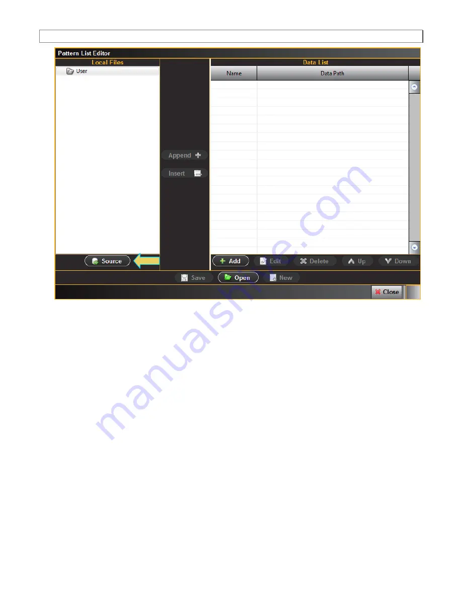
2. Click on the
Source
button on the lower left under Local Files (indicated in the diagram above). The Data
Source
dialog box will appear enabling you to select between using files on your PC or using files on the 980
DP 1.4 Video Generator / Analyzer module to create your custom list. This dialog box also enables you to
select the particular 980 (if there is more than one on the network). (You can also add a new 980 through this
dialog box.)
Note
: “Local Files” when using the external 980 GUI Manager means that you are using the files stored locally
on your host PC. If you deselect Local Files on the dialog box below you are viewing files on the 980 file
system.
Содержание 980 DP1.4
Страница 11: ...980 DP 1 4 Video Generator Analyzer User Guide Rev A1 Page 11 June 16 2017 ...
Страница 12: ...980 DP 1 4 Video Generator Analyzer User Guide Rev A1 Page 12 June 16 2017 ...
Страница 13: ...980 DP 1 4 Video Generator Analyzer User Guide Rev A1 Page 13 June 16 2017 ...
Страница 30: ...980 DP 1 4 Video Generator Analyzer User Guide Rev A1 Page 30 June 16 2017 ...
Страница 31: ...980 DP 1 4 Video Generator Analyzer User Guide Rev A1 Page 31 June 16 2017 ...
Страница 34: ...980 DP 1 4 Video Generator Analyzer User Guide Rev A1 Page 34 June 16 2017 ...
Страница 52: ...980 DP 1 4 Video Generator Analyzer User Guide Rev A1 Page 52 June 16 2017 ...
Страница 56: ...980 DP 1 4 Video Generator Analyzer User Guide Rev A1 Page 56 June 16 2017 View the Link Sink Status registers ...
Страница 57: ...980 DP 1 4 Video Generator Analyzer User Guide Rev A1 Page 57 June 16 2017 View the Test Automation registers ...
Страница 58: ...980 DP 1 4 Video Generator Analyzer User Guide Rev A1 Page 58 June 16 2017 View the Source Specific registers ...
Страница 59: ...980 DP 1 4 Video Generator Analyzer User Guide Rev A1 Page 59 June 16 2017 View the Sink Specific registers ...
Страница 60: ...980 DP 1 4 Video Generator Analyzer User Guide Rev A1 Page 60 June 16 2017 View the Branch Specific register ...
Страница 61: ...980 DP 1 4 Video Generator Analyzer User Guide Rev A1 Page 61 June 16 2017 View the Sink Control registers ...
Страница 63: ...980 DP 1 4 Video Generator Analyzer User Guide Rev A1 Page 63 June 16 2017 ...
Страница 64: ...980 DP 1 4 Video Generator Analyzer User Guide Rev A1 Page 64 June 16 2017 ...
Страница 81: ...980 DP 1 4 Video Generator Analyzer User Guide Rev A1 Page 81 June 16 2017 ...
Страница 91: ...980 DP 1 4 Video Generator Analyzer User Guide Rev A1 Page 91 June 16 2017 ...
Страница 104: ...980 DP 1 4 Video Generator Analyzer User Guide Rev A1 Page 104 June 16 2017 ...
Страница 119: ...980 DP 1 4 Video Generator Analyzer User Guide Rev A1 Page 119 June 16 2017 ...
Страница 121: ...980 DP 1 4 Video Generator Analyzer User Guide Rev A1 Page 121 June 16 2017 ...
Страница 128: ...980 DP 1 4 Video Generator Analyzer User Guide Rev A1 Page 128 June 16 2017 ...
Страница 145: ...980 DP 1 4 Video Generator Analyzer User Guide Rev A1 Page 145 June 16 2017 ...
Страница 154: ...980 DP 1 4 Video Generator Analyzer User Guide Rev A1 Page 154 June 16 2017 ...
Страница 156: ...980 DP 1 4 Video Generator Analyzer User Guide Rev A1 Page 156 June 16 2017 ...
Страница 160: ...980 DP 1 4 Video Generator Analyzer User Guide Rev A1 Page 160 June 16 2017 ...
Страница 162: ...980 DP 1 4 Video Generator Analyzer User Guide Rev A1 Page 162 June 16 2017 ...
Страница 168: ...980 DP 1 4 Video Generator Analyzer User Guide Rev A1 Page 168 June 16 2017 ...
Страница 173: ...980 DP 1 4 Video Generator Analyzer User Guide Rev A1 Page 173 June 16 2017 ...
Страница 175: ...980 DP 1 4 Video Generator Analyzer User Guide Rev A1 Page 175 June 16 2017 ...
Страница 178: ...980 DP 1 4 Video Generator Analyzer User Guide Rev A1 Page 178 June 16 2017 ...
Страница 187: ...980 DP 1 4 Video Generator Analyzer User Guide Rev A1 Page 187 June 16 2017 ...
Страница 224: ...980 DP 1 4 Video Generator Analyzer User Guide Rev A1 Page 224 June 16 2017 ...
Страница 231: ...980 DP 1 4 Video Generator Analyzer User Guide Rev A1 Page 231 June 16 2017 ...
Страница 236: ...980 DP 1 4 Video Generator Analyzer User Guide Rev A1 Page 236 June 16 2017 ...
Страница 245: ...980 DP 1 4 Video Generator Analyzer User Guide Rev A1 Page 245 June 16 2017 ...
Страница 246: ...980 DP 1 4 Video Generator Analyzer User Guide Rev A1 Page 246 June 16 2017 ...
Страница 247: ...980 DP 1 4 Video Generator Analyzer User Guide Rev A1 Page 247 June 16 2017 ...
Страница 248: ...980 DP 1 4 Video Generator Analyzer User Guide Rev A1 Page 248 June 16 2017 ...
Страница 249: ...980 DP 1 4 Video Generator Analyzer User Guide Rev A1 Page 249 June 16 2017 ...
Страница 250: ...980 DP 1 4 Video Generator Analyzer User Guide Rev A1 Page 250 June 16 2017 ...
Страница 251: ...980 DP 1 4 Video Generator Analyzer User Guide Rev A1 Page 251 June 16 2017 ...
Страница 255: ...980 DP 1 4 Video Generator Analyzer User Guide Rev A1 Page 255 June 16 2017 ...
Страница 275: ...980 DP 1 4 Video Generator Analyzer User Guide Rev A1 Page 275 June 16 2017 ...
Страница 277: ...980 DP 1 4 Video Generator Analyzer User Guide Rev A1 Page 277 June 16 2017 ...
Страница 282: ...980 DP 1 4 Video Generator Analyzer User Guide Rev A1 Page 282 June 16 2017 ...
Страница 292: ...980 DP 1 4 Video Generator Analyzer User Guide Rev A1 Page 292 June 16 2017 ...
Страница 295: ...980 DP 1 4 Video Generator Analyzer User Guide Rev A1 Page 295 June 16 2017 ...
Страница 358: ...980 DP 1 4 Video Generator Analyzer User Guide Rev A1 Page 358 June 16 2017 ...
Страница 388: ...980 DP 1 4 Video Generator Analyzer User Guide Rev A1 Page 388 June 16 2017 16 78 HalfClk 16 78 1Description ...
Страница 404: ...980 DP 1 4 Video Generator Analyzer User Guide Rev A1 Page 404 June 16 2017 16 93 HSVnRGB 16 93 1Description ...
Страница 405: ...980 DP 1 4 Video Generator Analyzer User Guide Rev A1 Page 405 June 16 2017 16 94 Imex1 16 94 1Description ...
Страница 417: ...980 DP 1 4 Video Generator Analyzer User Guide Rev A1 Page 417 June 16 2017 16 104 MAGENTA 16 104 1 Description ...
Страница 418: ...980 DP 1 4 Video Generator Analyzer User Guide Rev A1 Page 418 June 16 2017 16 105 Master 16 105 1 Description ...
Страница 425: ...980 DP 1 4 Video Generator Analyzer User Guide Rev A1 Page 425 June 16 2017 16 112 Monoscope 16 112 1 Description ...
Страница 427: ...980 DP 1 4 Video Generator Analyzer User Guide Rev A1 Page 427 June 16 2017 16 114 MulBurst 16 114 1 Description ...
Страница 491: ...980 DP 1 4 Video Generator Analyzer User Guide Rev A1 Page 491 June 16 2017 16 168 Taffeta 16 168 1 Description ...
Страница 495: ...980 DP 1 4 Video Generator Analyzer User Guide Rev A1 Page 495 June 16 2017 16 172 TintAlign 16 172 1 Description ...