A – Operating Theory
A-10
© Teledyne TSS
DPN 402196 Issue 4.1
A.2.5 Trenching Vehicles
In the case of a crawling ROV, it may not be possible to lift the vehicle off the seabed. However, very
good survey information can still be obtained merely by selecting the correct water temperature.
A.2.6 Limitations
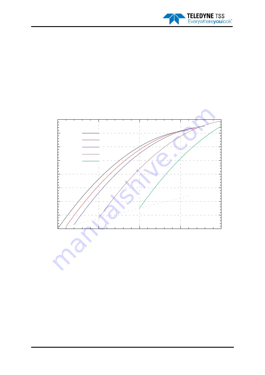
shows typical lift curves with a fixed target is present. Although this situation does not
appear when surveying, it shows how the software has to separate the seawater and target
components of the returned voltages. The solid curve (“No target”) shows a seawater lift curve with
only seawater present. If a 10µV target signal is present, then this curve will be repeated, but shifted
10µV to the right, and 30µV upwards. At an early voltage of approximately 140µV, this curve crosses
the “No target” curve.
Figure A-10: Typical lift curves with a fixed target present
This means that if the seawater rejection mechanism is faced with early and standard voltages of 140
and 1450µV, it will be unable to decide if a target is present or not. This means that at 140µV of
seawater, the algorithm will not work correctly and return a less accurate value for range. However, this
point occurs only when the ROV is approximately 4m above the seabed, well beyond the range of a
typical survey.
In more conductive water, the seawater parameters change, and the crossing point moves to perhaps
250µV. The increase in seawater signal means that the point where the algorithm begins to break
down remains at roughly 4m.
A sudden jump in the target voltages when the ROV is lifted is to be expected, and is not due to a
deficiency in the system or its configuration.
0
200
400
600
800
1000
1200
1400
1600
0
50
100
150
200
Early
V
oltage
Standard Voltage
Lift curves with fixed target present
m=17, g=-0.05
No target
10uV
20uV
50uV
100uV
Содержание 440
Страница 12: ...List of Figures x Teledyne TSS DPN 402196 Issue 4 1 ...
Страница 16: ...Revision History xiv Teledyne TSS DPN 402196 Issue 4 1 1 0 Feb 19 2003 First Issue Issue No Date Details ...
Страница 18: ...Glossary xvi Teledyne TSS DPN 402196 Issue 4 1 ...
Страница 24: ...1 Introduction 1 6 Teledyne TSS DPN 402196 Issue 4 1 ...
Страница 32: ...2 System Overview 2 8 Teledyne TSS DPN 402196 Issue 4 1 ...
Страница 66: ...4 Electrical Installation 4 20 Teledyne TSS DPN 402196 Issue 4 1 ...
Страница 88: ...5 Operating Software 5 22 Teledyne TSS DPN 402196 Issue 4 1 Figure 5 10 Altimeter Test ...
Страница 144: ...6 Operating Procedure 6 40 Teledyne TSS DPN 402196 Issue 4 1 ...
Страница 154: ...7 Operational Considerations 7 10 Teledyne TSS DPN 402196 Issue 4 1 ...
Страница 164: ...8 System Specifications 8 10 Teledyne TSS DPN 402196 Issue 4 1 ...
Страница 203: ...10 System Drawings DPN 402196 Issue 4 1 Teledyne TSS 10 17 Figure 10 15 SDC10 Dimensions ...
Страница 204: ...10 System Drawings 10 18 Teledyne TSS DPN 402196 Issue 4 1 Figure 10 16 400604 1 Power Supply Chassis Assembly ...
Страница 205: ...10 System Drawings DPN 402196 Issue 4 1 Teledyne TSS 10 19 Figure 10 17 400667 1 Main Chassis Assembly ...
Страница 206: ...10 System Drawings 10 20 Teledyne TSS DPN 402196 Issue 4 1 Figure 10 18 400667 2 Main Chassis Assembly ...
Страница 209: ...10 System Drawings DPN 402196 Issue 4 1 Teledyne TSS 10 23 Figure 10 21 400654 1 PSU Filter Assembly ...
Страница 210: ...10 System Drawings 10 24 Teledyne TSS DPN 402196 Issue 4 1 Figure 10 22 490232 1 Processor Pod Assembly ...
Страница 211: ...10 System Drawings DPN 402196 Issue 4 1 Teledyne TSS 10 25 Figure 10 23 490228 1 Power Supply Pod Assembly 110v version ...
Страница 212: ...10 System Drawings 10 26 Teledyne TSS DPN 402196 Issue 4 1 Figure 10 24 500045 1 Coil Mounting Frame ...
Страница 213: ...10 System Drawings DPN 402196 Issue 4 1 Teledyne TSS 10 27 Figure 10 25 B930892 1 Coil Assembly ...
Страница 214: ...10 System Drawings 10 28 Teledyne TSS DPN 402196 Issue 4 1 Figure 10 26 601004 1 Coil Cable Assembly ...
Страница 215: ...10 System Drawings DPN 402196 Issue 4 1 Teledyne TSS 10 29 Figure 10 27 B930473 1 PSU to ROV PWR COMMS Cable 3 0m ...
Страница 230: ...A Operating Theory A 12 Teledyne TSS DPN 402196 Issue 4 1 ...
Страница 242: ...B Options B 12 Teledyne TSS DPN 402196 Issue 4 1 ...
Страница 244: ...C Altimeter C 2 Teledyne TSS DPN 402196 Issue 4 1 ...
Страница 246: ...D Reference D 2 Teledyne TSS DPN 402196 Issue 4 1 ...
Страница 248: ...D Reference D 4 Teledyne TSS DPN 402196 Issue 4 1 ...
Страница 250: ...D Reference D 6 Teledyne TSS DPN 402196 Issue 4 1 ...
Страница 252: ...D Reference D 8 Teledyne TSS DPN 402196 Issue 4 1 ...
Страница 254: ...D Reference D 10 Teledyne TSS DPN 402196 Issue 4 1 ...


