


9 – Maintenance
DPN 402196 Issue 4.1
© Teledyne TSS
9- 5
After the initial 250V spike, the signal returned from the search-coil represents the voltage induced in
the target by the original current pulse.
The Analogue Board applies two stages of pre-amplification to each signal channel with an overall gain
of 200. If the SEP receives a signal that is too strong, the DSP removes the second stage of
amplification to reduce the overall gain to 10.
The Analogue Board removes noise using an intelligent filter that clamps the signal to zero until the
end of the 250V spike.
The conditioned signal then passes to the Main Board for processing and analysis.
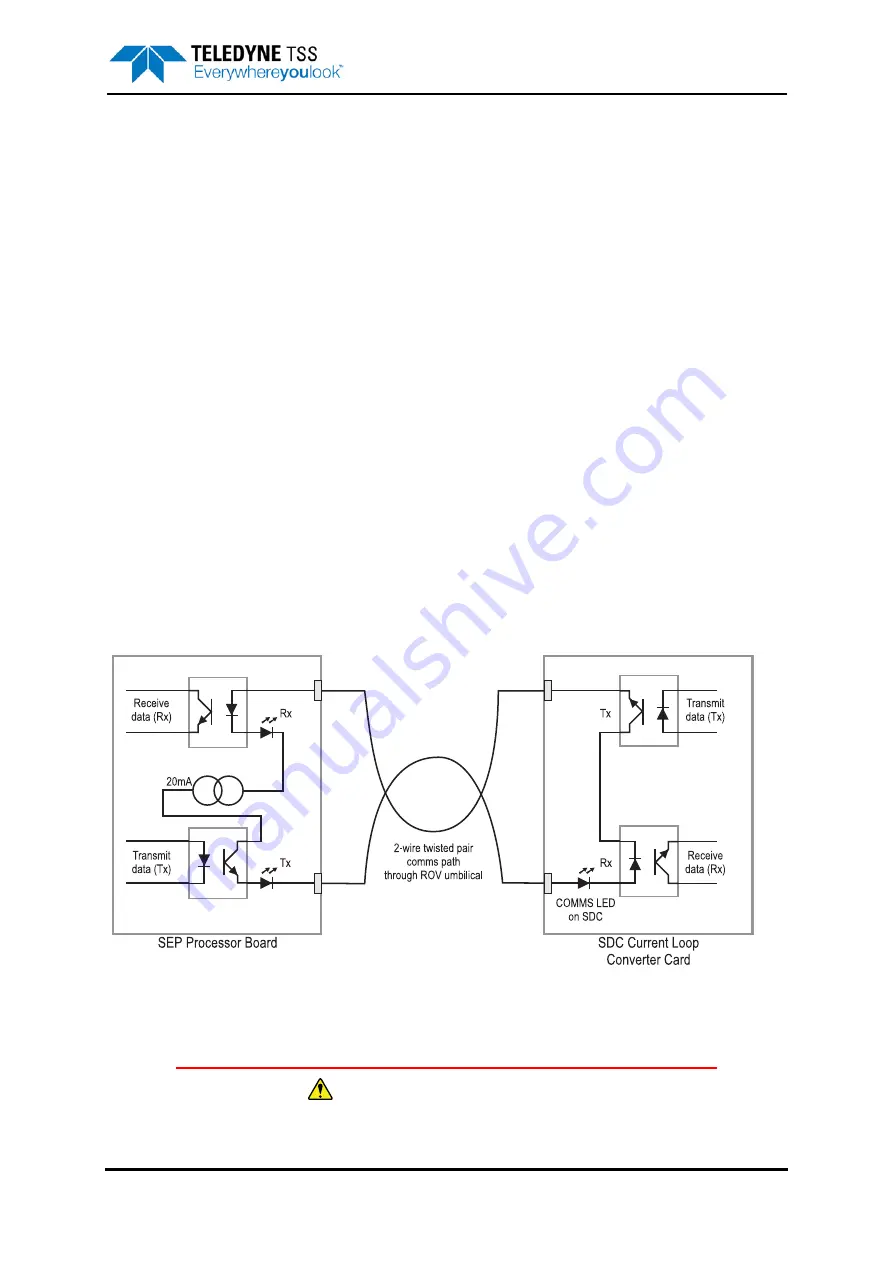
9.1.3 Communications Loop
When you configure the System to use the 2-wire current-loop communications method, the SEP and
the SDC share a twisted pair in the umbilical. To avoid possible contention, the 440 System assigns
‘Master’ status to the SDC, and ‘Slave’ status to the SEP.
Immediately after you power-on the 440 System, the SEP transmits a short ‘banner’ message to the
SDC and then waits for commands to arrive. Other than its initial banner message, the SEP will not
transmit any data until it receives a carriage-return signal from the SDC.
The SEP Main Board generates current at 20mA for the communication loop. The ‘COMMS’ LED on
the SDC is in series with the current-loop and therefore confirms that the communication loop is intact
when it shows red. Note that the COMMS LED does NOT confirm successful communication between
the SEP and SDC, but shows only that the loop is intact.
Figure 9-3 shows a simplified schematic of the current-loop, including the optically isolated I/O ports at
both ends of the umbilical cable.
Figure 9-3: Simplified schematic of the current-loop
9.2 Disassembly and Reassembly
WARNING - ELECTRICAL HAZARD
Mains power supply voltages can cause death or serious injury by electric shock.
Содержание 440
Страница 12: ...List of Figures x Teledyne TSS DPN 402196 Issue 4 1 ...
Страница 16: ...Revision History xiv Teledyne TSS DPN 402196 Issue 4 1 1 0 Feb 19 2003 First Issue Issue No Date Details ...
Страница 18: ...Glossary xvi Teledyne TSS DPN 402196 Issue 4 1 ...
Страница 24: ...1 Introduction 1 6 Teledyne TSS DPN 402196 Issue 4 1 ...
Страница 32: ...2 System Overview 2 8 Teledyne TSS DPN 402196 Issue 4 1 ...
Страница 66: ...4 Electrical Installation 4 20 Teledyne TSS DPN 402196 Issue 4 1 ...
Страница 88: ...5 Operating Software 5 22 Teledyne TSS DPN 402196 Issue 4 1 Figure 5 10 Altimeter Test ...
Страница 144: ...6 Operating Procedure 6 40 Teledyne TSS DPN 402196 Issue 4 1 ...
Страница 154: ...7 Operational Considerations 7 10 Teledyne TSS DPN 402196 Issue 4 1 ...
Страница 164: ...8 System Specifications 8 10 Teledyne TSS DPN 402196 Issue 4 1 ...
Страница 203: ...10 System Drawings DPN 402196 Issue 4 1 Teledyne TSS 10 17 Figure 10 15 SDC10 Dimensions ...
Страница 204: ...10 System Drawings 10 18 Teledyne TSS DPN 402196 Issue 4 1 Figure 10 16 400604 1 Power Supply Chassis Assembly ...
Страница 205: ...10 System Drawings DPN 402196 Issue 4 1 Teledyne TSS 10 19 Figure 10 17 400667 1 Main Chassis Assembly ...
Страница 206: ...10 System Drawings 10 20 Teledyne TSS DPN 402196 Issue 4 1 Figure 10 18 400667 2 Main Chassis Assembly ...
Страница 209: ...10 System Drawings DPN 402196 Issue 4 1 Teledyne TSS 10 23 Figure 10 21 400654 1 PSU Filter Assembly ...
Страница 210: ...10 System Drawings 10 24 Teledyne TSS DPN 402196 Issue 4 1 Figure 10 22 490232 1 Processor Pod Assembly ...
Страница 211: ...10 System Drawings DPN 402196 Issue 4 1 Teledyne TSS 10 25 Figure 10 23 490228 1 Power Supply Pod Assembly 110v version ...
Страница 212: ...10 System Drawings 10 26 Teledyne TSS DPN 402196 Issue 4 1 Figure 10 24 500045 1 Coil Mounting Frame ...
Страница 213: ...10 System Drawings DPN 402196 Issue 4 1 Teledyne TSS 10 27 Figure 10 25 B930892 1 Coil Assembly ...
Страница 214: ...10 System Drawings 10 28 Teledyne TSS DPN 402196 Issue 4 1 Figure 10 26 601004 1 Coil Cable Assembly ...
Страница 215: ...10 System Drawings DPN 402196 Issue 4 1 Teledyne TSS 10 29 Figure 10 27 B930473 1 PSU to ROV PWR COMMS Cable 3 0m ...
Страница 230: ...A Operating Theory A 12 Teledyne TSS DPN 402196 Issue 4 1 ...
Страница 242: ...B Options B 12 Teledyne TSS DPN 402196 Issue 4 1 ...
Страница 244: ...C Altimeter C 2 Teledyne TSS DPN 402196 Issue 4 1 ...
Страница 246: ...D Reference D 2 Teledyne TSS DPN 402196 Issue 4 1 ...
Страница 248: ...D Reference D 4 Teledyne TSS DPN 402196 Issue 4 1 ...
Страница 250: ...D Reference D 6 Teledyne TSS DPN 402196 Issue 4 1 ...
Страница 252: ...D Reference D 8 Teledyne TSS DPN 402196 Issue 4 1 ...
Страница 254: ...D Reference D 10 Teledyne TSS DPN 402196 Issue 4 1 ...