background image

P6106A Passive Probe

2

P6106A Instruction Manual

Installation

This section describes both attaching the probe to an oscilloscope and using the
standard accessories with the probe.

The probe uses a BNC connector to attach to an oscilloscope input connector. To
ensure optimum performance from your probe/oscilloscope measurement
system, verify that the probe and oscilloscope are appropriately matched. The
oscilloscope input impedance should be 1 M

W

. The oscilloscope input capaci-

tance should be between 15 and 35 pF. Refer to “Compensation Range” in
Table 1 on page 8 for more information.

Your P6106A is shipped with the following accessories:

H

This instruction manual—Read these instructions to familiarize yourself
with he features, specifications, and operation of the P6106A passive probe.

H

Accessory pouch—(not shown) Use the accessory pouch to store the probe
and its accessories when they are not being used.

H

Adjustment tool—Use the insulated adjustment tool to adjust the low
frequency trimmer in the probe compensation box.

H

IC protector tip—Use the IC protector tip to keep the metal sleeve of the
probe tip from accidentally shorting together the leads of an IC or other
circuit element. The shape of the protector tip helps you place the tip
accurately onto an IC lead.

H

Retractable hook tip—Use the retractable hook tip to make hands-free
measurements. The hook tip attaches to components having leads, such as
resistors, capacitors, and discrete semiconductors. You can also grip stripped
wire, jumpers, busses, and test pins with the retractable hook.

For maximum flexibility with the hook tip, use the twelve-inch ground lead.
For precise measurements at high frequency, however, long ground leads
may have too much inductance. In these cases you should use the five-inch
ground lead.

To remove the hook tip, simply pull it off the probe. Reinstall it by pushing
it firmly onto the probe tip.

H

Ground cover—Use the protective ground cover to keep the metal sleeve of
the probe tip from accidentally shorting circuit elements to ground. Remove
the ground cover before installing the retractable hook tip. 

H

Marker rings—Use the marker rings to help you keep track of individual
probes and signal sources when you have a complicated test setup. Use the
marker rings whenever you want to identify a particular probe for any

Attaching the Probe to an

Oscilloscope

Using the Standard

Accessories

Содержание P6106A

Страница 1: ...03 P070551703 070551703 Warning The servicing instructions are for use by qualified personnel only To avoid personal injury do not perform any servicing unless you are qualified to do so Refer to all safety summaries prior to performing service www tektronix com ...

Страница 2: ... and foreign patents issued and pending Information in this publication supercedes that in all previously published material Specifications and price change privileges reserved Tektronix Inc P O Box 500 Beaverton OR 97077 TEKTRONIX and TEK are registered trademarks of Tektronix Inc ...

Страница 3: ... charges for products returned to any other locations This warranty shall not apply to any defect failure or damage caused by improper use or improper or inadequate maintenance and care Tektronix shall not be obligated to furnish service under this warranty a to repair damage resulting from attempts by personnel other than Tektronix representatives to install repair or service the product b to rep...

Страница 4: ...a contact your local Tektronix distributor or sales office Service support Tektronix offers extended warranty and calibration programs as options on many products Contact your local Tektronix distributor or sales office For a listing of worldwide service centers visit our web site For other information In North America 1 800 833 9200 An operator can direct your call To write us Web site Tektronix ...

Страница 5: ... further ratings information before making connections to the product The common terminal is at ground potential Do not connect the common terminal to elevated voltages Do not apply a potential to any terminal including the common terminal that exceeds the maximum rating of that terminal Do Not Operate With Suspected Failures If you suspect there is damage to this product have it inspected by qual...

Страница 6: ...m service procedures Read this Service Safety Summary and the General Safety Summary before performing any service procedures Do Not Service Alone Do not perform internal service or adjustments to this product unless another person capable of rendering first aid and resuscitation is present ...

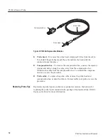
Страница 7: ...eplaceable Parts An exploded view of the probe and a list of replaceable parts Description The P6106A is a miniature 10X attenuating passive probe that is compatible with general purpose oscilloscopes having a 1 MW input impedance The P6106A is compatible with Tektronix oscilloscopes that automatically detect and display the attenuation factor of the attached probe The P6106A has a ground referenc...

Страница 8: ...eeve of the probe tip from accidentally shorting together the leads of an IC or other circuit element The shape of the protector tip helps you place the tip accurately onto an IC lead H Retractable hook tip Use the retractable hook tip to make hands free measurements The hook tip attaches to components having leads such as resistors capacitors and discrete semiconductors You can also grip stripped...

Страница 9: ...ed screw it onto the threaded end of the lead H Five inch ground lead Use the long ground lead when a long reach is important and high frequency information is not Because of the high inductance associated with long ground leads you should not use them for precise measurements above approximately 30 MHz or for pulses with rise times less than about 11 ns Long ground leads are ideal for quick troub...

Страница 10: ...tput of the probe to ground the signal under test is not affected Using the ground reference push button allows you to quickly note or verify the ground reference of a DC measurement If your oscilloscope is displaying several traces pressing the ground reference push button also helps you to identify which trace is associated with the probe WARNING To avoid electric shock when using the probe keep...

Страница 11: ...ncy is above the frequency at which you want to take measurements To maintain the best signal integrity use the shortest possible ground lead and signal input path Passive probes require compensation to ensure maximum distortion free output and to avoid high frequency amplitude errors Because of variations in oscilloscope input characteristics probe low frequency LF compensation may need adjustmen...

Страница 12: ...nt The probe high frequency compensation should seldom require adjustment however your probe may require high frequency adjustment if any of the following are true H the probe has excessive high frequency aberrations H the probe does not perform at the rated bandwidth H you have installed the probe on an oscilloscope having an input capacitance near the limits of the probe compensation range see T...

Страница 13: ...our oscilloscope Adjust your oscilloscope to 5 ns division The display should be similar to that shown in Figure 4 a a Area Of Waveform Affected By Trimmers b Location of Trimmers LF R2 R3 R5 C3 R3 R5 C3 R2 Figure 4 Adjusting High Frequency Compensation 3 Adjust R2 to flatten the first 40 ns of the waveform 4 Adjust R3 to flatten the first 20 ns of the waveform You may need to alternately adjust R...

Страница 14: ...250 MHz Maximum Input Voltage3 4 450 V RMS CAT I or 450 V DC CAT I 300 V RMS CAT II or 300 V DC CAT II 150 V RMS CAT III or 150 V DC CAT III 630 V peak 50 DF 1 sec PW 1000 V peak 20 DF 1 sec PW 1050 V peak 10 DF 50 ms PW See Figure 7 for voltage derating curve 1 Probe installed on Tektronix 475A 7A26 or equivalent 250 MHz oscilloscope 2 System characteristic 3 As defined in EN61010 1 See Certifica...

Страница 15: ... Factor 1 414 Peak V RMS Special case of square wave 20 Duty Factor VPeak 2 Duty Factor 1 2 Example Maximum Input Voltage 1000 V Pk 2 20 1 2 450 V RMS 0 V 0 V 0 V Figure 5 Maximum input voltage calculation example ohms Frequency Hz Phase degrees Z in Figure 6 Input Impedance by Frequency ...

Страница 16: ...lative Humidity Altitude 2000 meters 1 Tek Standard 062 2847 00 class 3 Refer to MIL E 16400F paragraph 4 5 9 through 4 5 9 5 1 class 4 Table 3 Certifications and compliances EC Declaration of Conformity Compliance was demonstrated to the following specification as listed in the Official Journal of the European Communities Low Voltage Directive 73 23 EEC as amended by 93 68 EEC EN 61010 1 A2 EN 61...

Страница 17: ...will help you maintain your probe for a long service life To prevent damage to probe materials avoid using chemicals that contain benzene toluene xylene acetone or similar solvents Remove accumulated loose dust from the probe exterior using a soft cloth or small brush Remaining dirt may be removed with a soft cloth dampened with a mild detergent and water solution or isopropyl alcohol Do not immer...

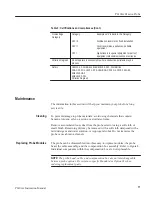
Страница 18: ...ew the tapered retainer and slide it along the cable away from the compensation box Withdraw the cable from the compensation box To reinstall the compensa tion box reverse the procedure H Probe cable To replace the probe cable remove the probe head and compensation box as described above To reassemble your probe reverse the procedure Replacement probe tips are available as optional accessories Ins...

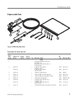
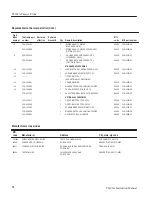
Страница 19: ...BOX ASSY 2 0 METER STANDARD ONLY COMP BOX ASSY 1 0 METER OPTION 01 ONLY 80009 80009 206 0319 01 206 0313 01 2 131 3219 00 1 CONN RCPT ELEC BNC MALE 24931 28P266 3 3 200 3016 00 1 COVER COMP BOX TOP ABS DOVE GRAY 80009 200 3016 00 4 200 3017 00 1 COVER COMP BOX BOTTOM ABS SLATE GRAY 80009 200 3017 00 5 200 3018 00 1 COVER CABLE NIP COMP BOX 0J260 ORDER BY DESC 6 174 0976 00 174 0975 00 1 1 CABLE AS...

Страница 20: ...OVER GROUND 80009 166 0404 01 14 016 0633 00 1 MARKER SET CA 2 EA VARIOUS COLORS 80009 016 0633 00 15 016 1644 00 1 POUCH ACCESSORY 6 25 X 9 25 80009 016 1644 00 070 5517 03 1 SHEET TECHNICAL INSTRUCTION P6106A 80009 070 5517 03 OPTIONAL ACCESSORIES 015 0201 07 1 TIP PROBE IC TEST PKG OF 10 80009 015 0201 07 015 0201 08 1 TIP PROBE IC TEST PKG OF 100 80009 015 0201 08 003 1433 02 1 SCREWDRIVER ADJ...

Отзывы: