background image

Connecting probes

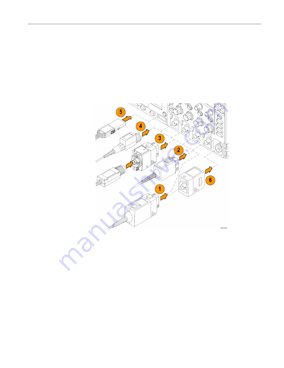
The oscilloscope supports probes with the following:

1.

Tektronix Versatile Probe Interface (TekVPI)

These probes support two-way communication with the oscilloscope through
on-screen menus and remotely through programmable support. The remote
control is useful in applications like ATE where you want the system to
preset probe parameters. 

2.

Tektronix Versatile Probe Interface (TekVPI) for Passive Probes

These probes build upon the functionality of the TekVPI interface. Each
probe is matched with its corresponding oscilloscope channel, allowing the
oscilloscope to optimize the signal input path. This provides AC
compensation across the frequency band.  

3.

TPA-BNC Adapter

The TPA-BNC Adapter allows you to use TEKPROBE II probe capabilities,
such as providing probe power, and passing scaling and unit information to
the oscilloscope. 


Installation

MDO4000C Series Oscilloscope User Manual 

9

Preliminary

Содержание MDO4000C Series

Страница 1: ...MDO4000C Series Mixed Domain Oscilloscope User Manual P077116700 077 1167 00 P r e l i m i n a r y...

Страница 2: ...P r e l i m i n a r y...

Страница 3: ...Warning The servicing instructions are for use by qualified personnel only To avoid personal injury do not perform any servicing unless you are qualified to do so Refer to all safety summaries prior...

Страница 4: ...g Information in this publication supersedes that in all previously published material Specifications and price change privileges reserved TEKTRONIX and TEK are registered trademarks of Tektronix Inc...

Страница 5: ...oscope 11 Power On 11 Powering off the oscilloscope 12 Functional check 13 Compensating a TPP0500B or TPP1000 passive voltage probe 15 Compensating a non TPP0500B or non TPP1000 passive voltage probe...

Страница 6: ...digital channels 48 When and why to turn on MagniVu 50 Using MagniVu 51 Trigger setup Choosing a trigger type 53 Selecting triggers 54 Triggering on buses 57 Parallel bus trigger 58 I2C bus trigger 58...

Страница 7: ...waveforms 87 Using FFT 89 Using advanced math 92 Using spectrum math 93 Using reference waveforms and traces 94 Using wave inspector to manage long record length waveforms 96 Panning a waveform 96 Pla...

Страница 8: ...X passive probes information Operating information 127 Connecting the probe to the oscilloscope 127 Compensating the probe with the MDO4000C series oscilloscope 128 Standard accessories 128 Optional a...

Страница 9: ...addition to the safety precautions specified in this manual The product is designed to be used by trained personnel only Only qualified personnel who are aware of the hazards involved should remove t...

Страница 10: ...product Do not exceed the Measurement Category CAT rating and voltage or current rating of the lowest rated individual component of a product probe or accessory Use caution when using 1 1 test leads...

Страница 11: ...ling the product so it has proper ventilation Slots and openings are provided for ventilation and should never be covered or otherwise obstructed Do not push objects into any of the openings Provide a...

Страница 12: ...ope input BNC connector probe tip or probe reference lead Connect and disconnect properly Connect the probe output to the measurement product before connecting the probe to the circuit under test Conn...

Страница 13: ...rd from the mains power before removing any covers or panels or opening the case for servicing Use care when servicing with power on Dangerous voltages or currents may exist in this product Disconnect...

Страница 14: ...zard to property including the product Symbols on the product When this symbol is marked on the product be sure to consult the manual to find out the nature of the potential hazards and any actions wh...

Страница 15: ...t the immunity requirements of applicable listed standards when test leads and or test probes are connected due to coupling of electromagnetic interference onto those leads probes To minimize the infl...

Страница 16: ...ernment to carry the GOST mark Safety compliance This section lists the safety standards with which the product complies and other safety compliance information EU declaration of conformity low voltag...

Страница 17: ...ment Safety class Class 1 grounded product Pollution degree description A measure of the contaminants that could occur in the environment around and within a product Typically the internal environment...

Страница 18: ...ts performed on circuits directly connected to the low voltage installation Measurement Category III For measurements performed in the building installation Measurement Category IV For measurements pe...

Страница 19: ...t in an appropriate system that will ensure that most of the materials are reused or recycled appropriately This symbol indicates that this product complies with the applicable European Union requirem...

Страница 20: ...Compliance Information xvi MDO4000C Series Oscilloscope User Manual P r e l i m i n a r y...

Страница 21: ...GS s on all analog channels depending on the model 20 M points record length on all channels 340 000 waveforms second maximum waveform capture rate A dedicated RF input channel for frequency domain m...

Страница 22: ...cons are used throughout this manual Sequence Step Front panel power Connect power Network USB Warranty Three year warranty covering all parts and labor excluding probes Preface xviii MDO4000C Series...

Страница 23: ...nix com manuals Table 1 Standard accessories Accessory Description Tektronix part number MDO4000C Series Oscilloscopes User Manual Please find these manuals on www tektronix com manuals English Option...

Страница 24: ...Portuguese Option L6 SA version Non SA version 335 3604 XX 335 3614 XX Simplified Chinese Option L7 SA version Non SA version 335 3605 XX 335 3615 XX Traditional Chinese Option L8 SA version Non SA ve...

Страница 25: ...module This module enables triggering on MIL STD 1553 serial buses Also it provides digital views of the signal bus views bus decoding search tools and decode tables with time stamp information DPO4A...

Страница 26: ...32 RS 422 RS 485 and UART serial buses Also it provides digital views of the signal bus views packet decoding search tools and packet decode tables with time stamp information DPO4COMP Embedded serial...

Страница 27: ...g data in hex binary and ASCII search tools and packet decode tables with time stamp information NOTE 1 GHz bandwidth models are required for high speed HS USB DPO4USB Extended video application modul...

Страница 28: ...all application modules on your oscilloscope 071 3253 XX DPO3PWR and DPO4PWR Power Measurement Module User Manual English Option L0 071 2631 XX French Option L1 077 0235 XX Italian Option L2 077 0236...

Страница 29: ...ekProbe II BNC Adapter TPA BNC The MDO4000C Series oscilloscopes support a multitude of optional probes See Connecting probes on page 9 Visit the Oscilloscope Probe and Accessory Selector Tool on the...

Страница 30: ...dle and front flip feet to place the oscilloscope in a convenient operating position When the feet are extended always have the handle in a down position Installation 8 MDO4000C Series Oscilloscope Us...

Страница 31: ...onix Versatile Probe Interface TekVPI for Passive Probes These probes build upon the functionality of the TekVPI interface Each probe is matched with its corresponding oscilloscope channel allowing th...

Страница 32: ...probe provides 16 channels of digital on or off state information 6 The TPA N VPI Adapter allows you to use TekVPI probes in the RF input For more information on the many probes available for use with...

Страница 33: ...ower cord to the rear panel power connector 2 Push the power button on the instrument front panel and the instrument will turn on NOTE The Standby button on the front panel does not disconnect mains p...

Страница 34: ...Powering off the oscilloscope To power off the oscilloscope remove the power cord Installation 12 MDO4000C Series Oscilloscope User Manual P r e l i m i n a r y...

Страница 35: ...illoscope power cable See Power On on page 11 2 Power on the oscilloscope 3 Connect the probe connector to oscilloscope channel 1 and the probe tip and reference lead to the PROBE COMP terminals on th...

Страница 36: ...gnal appears but is misshapen perform the procedures for compensating the probe If no signal appears rerun the procedure If this does not remedy the situation have the instrument serviced by qualified...

Страница 37: ...tion 1 Connect the oscilloscope power cable See Power On on page 11 2 Power on the oscilloscope 3 Connect the probe connector to the oscilloscope channel and the probe tip and reference lead to the PR...

Страница 38: ...teps Each channel can store compensation values for 10 individual probes If you try to compensate an 11th probe on a channel the oscilloscope will delete the values for the least recently used probe a...

Страница 39: ...P1000 Tektronix passive probe check the instruction manual for your probe to see if it qualifies Otherwise to properly compensate your passive probe 1 Follow the steps for the functional check See Fun...

Страница 40: ...ll the module with the label facing away from you Some of the modules have licenses which allow you to transfer the license between your application modules and the oscilloscope You can keep each lice...

Страница 41: ...some other oscilloscope and wonders why it does not work Upgrading bandwidth You may increase the bandwidth of an instrument when your project requirements demand higher performance Do this by purchas...

Страница 42: ...200 MHz 500 MHz MDO4BW2T54 SA 200 MHz 1 GHz MDO4BW2T104 SA 350 MHz 500 MHz MDO4BW3T54 SA 350 MHz 1 GHz MDO4BW3T104 SA 500 MHz 1 GHz MDO4BW5T104 SA MDO4034C Yes 350 MHz 500 MHz MDO4BW3T54 SA 350 MHz 1...

Страница 43: ...pose knob a and select Config 4 Push Language from the resulting lower menu 5 Push Menus from the resulting side menu and turn multipurpose knob a to select the desired language for the user interface...

Страница 44: ...at you desire over the front panel to display labels in that language NOTE If you order a language option you will receive two front panel overlays in the language you ordered One for models with RF o...

Страница 45: ...ush Utility Page Utility Page 2 3 Turn multipurpose knob a and select Config 4 Push Set Date Time 5 Push the side menu buttons and turn both multipurpose knobs a and b to set the time and date values...

Страница 46: ...mV division or less Failure to do so may result in the instrument not meeting warranted performance levels at those volts div settings To compensate the signal path 1 Warm up the oscilloscope for at...

Страница 47: ...then recalibrate the instrument or have the instrument serviced by qualified service personnel Service personnel use the factory calibration functions to calibrate the internal voltage references of...

Страница 48: ...re downloads Proceed to the software finder Download the latest firmware for your oscilloscope on your PC Unzip the files and copy the firmware img file into the root folder of a USB flash drive or US...

Страница 49: ...s it If the instrument does not install the firmware rerun the procedure If the problem continues try a different model of USB flash or hard drive Finally if needed contact qualified service personnel...

Страница 50: ...Power on the oscilloscope 7 Push Utility 8 Push Utility Page Utility Page 8 9 Turn multipurpose knob a and select Config 10 Push About The oscilloscope displays the firmware version number Installati...

Страница 51: ...Also load your application such as OpenChoice Desktop You will find the drivers and OpenChoice Desktop software on the appropriate CD that comes with your oscilloscope or at the Tektronix software fi...

Страница 52: ...push Socket Server and enter new values through the resulting side menu 9 If you are using GPIB push GPIB Enter the GPIB address on the side menu by turning the Multipurpose a knob This will set the...

Страница 53: ...Change Ethernet LXI Password to change the name of the password 13 Push Change e Scope Password to use the LXI password to also protect your oscilloscope from changes made to LAN settings from a Web b...

Страница 54: ...t client Telnet which has a command interface One way to do this is by typing Telnet in the Run window The Telnet window will open on the PC NOTE On MS Windows 7 you must first enable Telnet in order...

Страница 55: ...ore queries and view more results using this Telnet session window You can find the syntax for relevant commands queries and related status codes in the MDO3000 Series Programmer Manual NOTE Do not us...

Страница 56: ...arrow keys on the keyboard to move the insertion point and then type in a name or label Labeling channels and buses makes the information on the screen easier to identify To choose whether to use a ke...

Страница 57: ...anel controls 2 10 digit keypad 3 Application module slots 4 Ground strap connector 5 Ground 6 PROBE COMP 7 Auxiliary Input only on instruments without option SA3 or SA6 8 Dedicated spectral analysis...

Страница 58: ...pulse as a 10 MHz reference signal or to output a signal when other events happen such as mask limit test events 3 REF IN Use the 10 MHz external reference input to provide an external timebase 4 LAN...

Страница 59: ...the USB2 0 specification for high speed operation when connected to a high speed host controller 7 USB 2 0 Host port Use the USB 2 0 High Speed Host port to connect a USB memory device or USB keyboar...

Страница 60: ...Get acquainted with the instrument 38 MDO4000C Series Oscilloscope User Manual P r e l i m i n a r y...

Страница 61: ...o acquire the signal as you want it to Using the default setup To return the oscilloscope to its default settings 1 Push Default Setup 2 If you change your mind push Undo Default Setup to undo the las...

Страница 62: ...channel connect the analog probe and then select the input channel To autoset a digital channel connect the logic probe and select the input channel See Setting up digital channels on page 48 2 Push...

Страница 63: ...a stable video signal Using FastAcq FastAcq provides high speed waveform capture It is helpful in finding elusive signal anomalies Fast acquisition mode reduces the dead time between waveform acquisit...

Страница 64: ...quency of occurrence with colder colors like blue indicating frequently occurring events and hot colors like red indicating rarely occurring events Normal uses the default channel color like yellow fo...

Страница 65: ...f all the samples for each acquisition interval This mode also only works with real time noninterpolated sampling Hi Res provides a higher resolution lower bandwidth waveform Envelope mode finds the h...

Страница 66: ...mple Peak Detect Hi Res Envelope or Average Acquisition Mode Sample Peak Detect Hi Res Envelope Average 16 3 3 3 3 4 If you chose Average turn multipurpose knob a to set the number of waveforms to ave...

Страница 67: ...ntal expansion point stays at the center of the screen The trigger point can move off the screen When this happens the trigger marker turns to point in the direction of the trigger point Use the delay...

Страница 68: ...ms per division or faster Push Run Stop to halt Roll mode Act on Event Have the oscilloscope perform a defined action after a defined event has occurred The event can be a trigger or a certain number...

Страница 69: ...menu to define the parameters of the email NOTE There is a single set of SMTP server settings saved for both Act on Event e mail notification and for the e mail printer set through the Utility Print S...

Страница 70: ...the ground lead or leads to the circuit ground You can connect a separate lead for each channel or a common ground lead for each group of 8 wires 3 If needed connect the appropriate grabber for each p...

Страница 71: ...nnels at a glance 11 Push MagniVu on the lower menu to increase the timing resolution 12 Push Height on the lower menu repeatedly to set the signal height You only need to do this once to set the heig...

Страница 72: ...a maximum resolution of 60 6 ps for 10 000 points centered around the trigger NOTE MagniVu centers itself around the trigger point If you turn MagniVu on while using a large record length and you are...

Страница 73: ...increase the resolution MagniVu is always acquired If the oscilloscope is in a stopped state you can turn on MagniVu and still get the resolution without taking another acquisition The serial bus fea...

Страница 74: ...Acquire the signal 52 MDO4000C Series Oscilloscope User Manual P r e l i m i n a r y...

Страница 75: ...n module Using the bus trigger on other buses requires use of a DPO4AERO DPO4AUDIO DPO4AUTO DPO4AUTOMAX DPO4COMP DPO4EMBD DPO4ENET or DPO4USB application module 3 Turn multipurpose knob a to select th...

Страница 76: ...s for a specified number of B Events before triggering and displaying the waveform Pulse Width Trigger on pulses that are less than greater than equal to or not equal to a specified time Additionally...

Страница 77: ...ust first install the MDO4TRIG application module NOTE Optimum Logic trigger performance is achieved by using only analog channels or only digital channels Setup and Hold Trigger when a logic data inp...

Страница 78: ...video standard signals as well as custom non standard bilevel and trilevel video signals with 3 to 4 000 lines Bus Trigger on various bus conditions I2C requires a DPO4EMBD module SPI requires a DPO4E...

Страница 79: ...mation as digital and symbolic waveforms To set up the bus trigger 1 If you have not already defined your bus using the front panel B1 B2 or B3 buttons do so now 2 Push Trigger Menu 3 Push Type 4 Turn...

Страница 80: ...s on the side menu Enter the address parameters of interest with multipurpose knobs a and b Then push Direction on the lower menu and select the direction of interest Read Write or Read or Write If yo...

Страница 81: ...MOSI MISO push Data on the lower menu and enter the parameters of interest in the side menus RS 232 bus trigger You can trigger on Tx Start Bit Rx Start Bit Tx End of Packet Rx End of Packet Tx Data...

Страница 82: ...on the lower menu and select the direction of interest Read Write or Read or Write If you have made a Trigger On selection of Data push Data on the lower menu and enter the parameters of interest LIN...

Страница 83: ...r You can trigger on Sync Reset Suspend Resume End of Packet Token Address Packet Data Packet Handshake Packet Special Packet or Error NOTE For triggering on a high speed USB bus 480 MB s use an oscil...

Страница 84: ...on the lower menu to enter specific Data values and the Parity value If you are setting up a MIL STD 1553 trigger and have made a Trigger On selection of Time RT IMG push Trigger When on the lower men...

Страница 85: ...er parameters check the Trigger readout at the bottom of the display The readouts differ for edge and the advanced triggers 1 Trigger source channel 1 2 Trigger slope rising 3 Trigger level 0 00 V Tri...

Страница 86: ...event before stopping While waiting for the trigger event the Run Stop button will turn yellow and the Single button will turn green Once the acquisition occurs the Run Stop button will turn red and t...

Страница 87: ...aveform or trace Adding and removing a waveform 1 To add or remove a waveform from the display push the corresponding front panel channel button or the D15 D0 button You can use the channel as a trigg...

Страница 88: ...2 Rotate multipurpose knob a to select the desired waveform intensity 3 Rotate multipurpose knob b to select the desired intensity for the graticule 4 Push Intensity again to clear the intensity read...

Страница 89: ...button as many times as needed and the associated menu items to select add or remove a waveform Pushing the Vertical position control will center the waveform on the screen vertically and pushing the...

Страница 90: ...The math waveform cursors and automatic measurements remain active and valid when using preview Display waveform or trace data 68 MDO4000C Series Oscilloscope User Manual P r e l i m i n a r y...

Страница 91: ...d DC components Use AC coupling to block the DC component and show only the AC signal Coupling DC AC Termination 1M 50 Invert On Off Bandwidth Full 1 Label More 2 3 4 5 6 7 8 3 Push Termination repeat...

Страница 92: ...adjustments Push Set to 0 V on the side menu to set the vertical offset to 0 V For more information on offset see Quick Tips 11 Select Probe Setup to define probe parameters On the side menu Select V...

Страница 93: ...bes with the TekProbe II and TekVPI Interfaces When you attach a probe with the TekProbe II or the TekVPI interface the oscilloscope sets the channel sensitivity coupling and termination resistance au...

Страница 94: ...dit Labels Monitor MagniVu On Off Height S M L 2 6 4 Turn multipurpose knob a to select the channel to move 5 Turn multipurpose knob b to move the selected channel NOTE The display of the channel or g...

Страница 95: ...ome or all of the digital channels together move the channels right next to each other All the channels that are next to each other automatically form a group You can see the groups by pushing Select...

Страница 96: ...transitions you may be able to zoom in and see the individual edges When you are zoomed in so far that there is more than one pixel column per sample the uncertainty of the edge position is indicated...

Страница 97: ...e side menu The annotation window now appears Position it by turning multipurpose knobs a and b 6 Push Edit Annotation on the side menu 7 Turn multipurpose knob a to scroll through the list of letters...

Страница 98: ...cur To display this readout do the following 1 Push Utility 2 Push Utility Page Utility Page 2 3 Turn multipurpose knob a and select Display 4 Push Trigger Frequency Readout from the resulting lower m...

Страница 99: ...to measure on 5 To remove a measurement push Remove Measurement turn multipurpose knob a to select the specific measurement and push OK Remove Measurement on the side menu Quick Tips To remove all me...

Страница 100: ...he mid reference default 50 amplitude point of two different waveforms See also Phase Phase The amount of time that one waveform leads or lags another waveform expressed in degrees where 360 makes up...

Страница 101: ...histogram method uses the most common value found above the midpoint This value is measured over the entire waveform or gated region Low This value is used as 0 whenever high reference mid reference...

Страница 102: ...gated region Rising Edge Count The number of positive transitions from the low reference value to the high reference value in the waveform or gated region Falling Edge Count The number of negative tr...

Страница 103: ...age of the highest nonzero bin in vertical histograms or the time of the rightmost nonzero bin in horizontal histograms Histogram Min Displays the voltage of the lowest nonzero bin in vertical histogr...

Страница 104: ...elect each frequency measurement on screen help will appear to explain the purpose of that measurement A Configure item will appear on the lower menu After you press Configure and set the measurement...

Страница 105: ...and hold Cursors to display the cursor menu In this example two vertical cursors appear on the selected waveform As you turn multipurpose knob a you move one cursor to the right or left As you turn k...

Страница 106: ...n the graticule Cursors Waveform Screen Source Selected Waveform Bars Horizontal Vertical Linked On Off Bring Cursors On Screen Cursor Units 5 11 6 Turn multipurpose knobs a and b to move the pair of...

Страница 107: ...u again 11 Push Source on the lower menu A pop up menu will appear The default menu selection of Selected Waveform will cause the cursors to take measurements on the selected last used waveform 12 Tur...

Страница 108: ...sh Cursors again This turns off the cursors The screen no longer displays the cursors and the cursor readout Analyze waveform or trace data 86 MDO4000C Series Oscilloscope User Manual P r e l i m i n...

Страница 109: ...s 1 Push Math 2 Push Dual Wfm Math Dual Wfm Math FFT Advanced Math Spectrum Math M Label 2 3 On the side menu set the sources to either channel 1 2 3 4 or reference waveforms R1 2 3 or 4 Choose the x...

Страница 110: ...waveforms also adjusts the math waveform You can zoom in on math waveforms using the inner knob of the Pan Zoom control Use the outer knob for positioning the zoomed area See Using wave inspector to m...

Страница 111: ...power supplies 1 Push Math 2 Push FFT Dual Wfm Math FFT Advanced Math Spectrum Math M Label 2 3 Push FFT Source on the side menu if needed and turn multipurpose knob a to select the source to use Cho...

Страница 112: ...feature along with the horizontal Position and Scale controls to magnify and position the FFT waveform Use the default dBV RMS scale to see a detailed view of multiple frequencies even if they have ve...

Страница 113: ...e the Hamming window for measuring sine periodic and narrow band random noise This window works well on transients or bursts where the signal levels before and after the event are significantly differ...

Страница 114: ...xpressions 4 Push Edit Expression and use the multipurpose knobs and the resulting lower menu buttons to create an expression When done push OK Accept For example to use Edit Expression to take the in...

Страница 115: ...maximum trace RF M the RF minimum trace RF m or any of the reference memories with frequency domain information 4 Choose or as the operator 5 Choose the second source from the provided options The mat...

Страница 116: ...M reference waveforms are volatile and not saved when the oscilloscope power is turned off To keep these waveforms save them to external storage 1 Push Ref R This brings up the lower reference menu 2...

Страница 117: ...s at the same time Push the appropriate screen button to select a particular reference waveform Removing Reference Waveforms from the Display To remove a reference waveform from the display push R on...

Страница 118: ...om Control consists of 1 An outer pan knob 2 An inner zoom knob Panning a waveform While the zoom feature is on you can use the pan feature to quickly scroll through the waveform To use pan 1 Rotate t...

Страница 119: ...ction that you are turning the pan knob 4 During play up to a point the more you turn the ring the faster the waveform accelerates If you rotate the ring as far as it can go the play speed does not ch...

Страница 120: ...pes To manually set and clear delete marks 1 Move the zoom box to the area on the waveform where you want to set or clear a search mark by turning the pan outer knob Push the next or previous arrow bu...

Страница 121: ...stamped listing of each event 4 On the screen hollow triangles show the location of automatic marks and solid triangles show the custom user defined locations These appear on both normal and zoomed wa...

Страница 122: ...a way to magnify a portion of the record without having to use the smaller zoom screen display This feature gives you the maximum benefit of the sample rate record length combination in your oscillosc...

Страница 123: ...is 3 Push Analysis Application Analysis None 2 4 Use the side menu buttons to select the desired analysis function Choose among power quality switching loss harmonics ripple modulation and safe operat...

Страница 124: ...Analyze waveform or trace data 102 MDO4000C Series Oscilloscope User Manual P r e l i m i n a r y...

Страница 125: ...select the appropriate menu such as the To File side menu to save setups and waveforms and turn multipurpose knob a to scroll through the external file structure E is the USB memory device plugged int...

Страница 126: ...defines the trace and can be one of the following NRM for a normal trace AVG for an average trace MAX for a maximum hold trace MIN for a minimum hold trace AVT for an amplitude versus time trace FVT...

Страница 127: ...eform Save Setup Recall Waveform Recall Setup Assign Save to Setup File Utilities 2 2 2 3 For waveform or setup files enter the file manager by pushing the appropriate side menu button To File 3 4 Tur...

Страница 128: ...h the Menu Off button to cancel the save operation or push OK Save on the side menu to complete the operation Save and recall information 106 MDO4000C Series Oscilloscope User Manual P r e l i m i n a...

Страница 129: ...es for each point in the waveform To save a screen image 1 Push Save Recall Menu Do not yet push the Save button 2 Push Save Screen Image on the lower menu Save Screen Image Save Waveform Save Setup R...

Страница 130: ...n or off When on this mode provides a white background 6 Push Edit File Name to create a custom name for the screen image file Skip this step to use a default name 7 Push OK Save Screen Image to write...

Страница 131: ...e Save Waveform Save Setup Recall Waveform Recall Setup Assign Save to Setup File Utilities 2 2 3 From the resulting side menu select the location to save the setup to or to recall it from To save set...

Страница 132: ...u Off button to cancel the save operation or push Save to Selected File on the side menu to complete the operation 5 Save the file Save to Selected File 5 Quick Tips Recalling the Default Setup Push D...

Страница 133: ...urrent waveform data to the defined USB flash drive 1 To define the Save button behavior push Save Recall Menu 2 Push Assign Save to Save Screen Image Save Waveform Save Setup Recall Waveform Recall S...

Страница 134: ...ave the oscilloscope will perform the action that you just specified rather than requiring you to navigate through the menus each time Save and recall information 112 MDO4000C Series Oscilloscope User...

Страница 135: ...ave to Setup File Utilities 2 Select the desired file operation from the side menus You can Create a new folder Delete a highlighted directory or file Copy a highlighted drive directory or file Paste...

Страница 136: ...B keyboard or the on screen interface to enter the server name or IP address Path Use a USB keyboard or the on screen interface to enter the shared file path For example to mount an MS Windows PC dire...

Страница 137: ...was powered down will be automatically remounted when the oscilloscope is powered up Unmount any network location that you do not want to automatically remount on power up Save and recall information...

Страница 138: ...laces the current front panel setup and all stored setups with the default setup Displays a confirmation or warning message depending on whether the verification is successful or unsuccessful To use T...

Страница 139: ...6 Power off the oscilloscope and then power it back on to complete the process Save and recall information MDO4000C Series Oscilloscope User Manual 117 P r e l i m i n a r y...

Страница 140: ...Save and recall information 118 MDO4000C Series Oscilloscope User Manual P r e l i m i n a r y...

Страница 141: ...131 072 points of an arbitrary waveform You can create the waveform from any of the four internal ARB memories the four or two analog channels the four or two reference waveforms the math waveform or...

Страница 142: ...ption of your concept here optional To access the AFG output connect your cable to the port marked AFG OUT in the back of the oscilloscope Use the Arbitrary Function Generator 120 MDO4000C Series Osci...

Страница 143: ...rn the AFG output on and off The button lights up when the output is on The light goes out when it is off The On Off status is always off when you recall an instrument setup The AFG will always come u...

Страница 144: ...Use the Arbitrary Function Generator 122 MDO4000C Series Oscilloscope User Manual P r e l i m i n a r y...

Страница 145: ...to help you efficiently analyze your serial bus These include digital views of the signal bus views packet decoding search tools and event tables with timestamp information The DPO4AUTOMAX FlexRay CA...

Страница 146: ...erating area and slew rate dV dt and dI dt The DPO4USB USB 2 0 Serial Triggering and Analysis Module adds triggering and analysis on USB low speed full speed and high speed buses NOTE 1 GHz bandwidth...

Страница 147: ...a list of MDO4000C product specifications in the MDO4000C Series Oscilloscopes Specifications and Performance Verification Technical Reference Downloadable from www tektronix com manuals MDO4000C Ser...

Страница 148: ...Appendix A MDO4000C Series specifications 126 MDO4000C Series Oscilloscope User Manual P r e l i m i n a r y...

Страница 149: ...robes are compact passive probes with 10X attenuation that are designed for use with Tektronix MDO4000C Series oscilloscopes The probes have no user or Tektronix serviceable parts Connecting the probe...

Страница 150: ...then clamp the hook onto the circuit Reorder Tektronix part number 013 0362 XX Micro Hook tip Use this tip to access test points in tight spaces Press the hook tip onto the probe tip and then clamp th...

Страница 151: ...art numbers 016 2028 XX long 2 ea 016 2034 XX short 2 ea Optional accessories The following accessories can be ordered for your probe Accessory Tektronix part number Ground Lead Clip on 6 in 196 3198...

Страница 152: ...1 GHz System rise time typical 700 ps 450 ps System input capacitance Rigid tip 3 9 pF 0 3 pf Pogo pin tip 5 1 pf 0 5 pf System attenuation accuracy 10 1 2 2 Probe series resistance DC 9 75 M 0 5 Sys...

Страница 153: ...ing 15 C to 65 C 5 F to 149 F 62 C to 85 C 80 F to 185 F Humidity Operating Nonoperating 5 to 95 relative humidity up to 30 C 5 to 45 relative humidity 30 C up to 50 C Altitude Operating Nonoperating...

Страница 154: ...conductive pollutants may be present as defined in IEC 61010 1 Rated for indoor use only Additional Safety Standards UL61010B 1 First Edition UL61010B 2 031 First Edition CAN CSA C22 2 No 1010 1 92 CA...

Страница 155: ...ition mode 43 B B1 B2 B3 B4 57 Bandwidth xvii 70 Before Installation 1 Blackman Harris FFT window 91 Blue lines 73 BNC interface 10 Burst Width measurement 78 Bus button 57 Bus trigger defined 56 Buse...

Страница 156: ...calibration 25 Fall Time measurement 78 Falling Edge Count measurement 80 FFT Blackman Harris 91 controls 89 Hamming 91 Hanning 91 Rectangular 91 File names 104 Filesystem 103 Firmware upgrade 26 fir...

Страница 157: ...I2S 57 Impedance 69 Inner knob 88 Invert 69 K Keyboard Connection 34 Key layout style 34 language 21 Knob inner 88 pan 96 98 zoom 88 Knobs See Front panel controls L Language change 21 overlay 22 Left...

Страница 158: ...sition and offset 71 Positive Duty Cycle measurement 78 Positive Overshoot measurement 79 Positive Pulse Count measurement 80 Positive Pulse Width measurement 78 Pouch probe and accessory 3 Power cord...

Страница 159: ...Signal path compensation Time and frequency domains 24 Single button 64 Single sequence 64 Slew rate 5 Software optional 123 Spectrum Math 93 SPI 57 SPI bus trigger 58 Standard Deviation measurement...

Страница 160: ...uage 21 User marks 98 V Versatile Probe Interface 9 Vertical menu 69 offset 71 Offset 70 position 67 position and autoset 41 position and offset 71 scale 67 VESA mounts 37 Video Autoset 41 Video Out p...

Отзывы: