Teknion Navigate 120 HA Frame HNBFNT Скачать руководство пользователя страница 15

Section:
Description:

Page No:

Date: 

WORKSURFACE AND SWITCH-2

May 2022

15 of 18

HABN_123

120 HA FRAME

FRAMES AND WORKSURFACES

height-adjustable bench 

Installation Guides

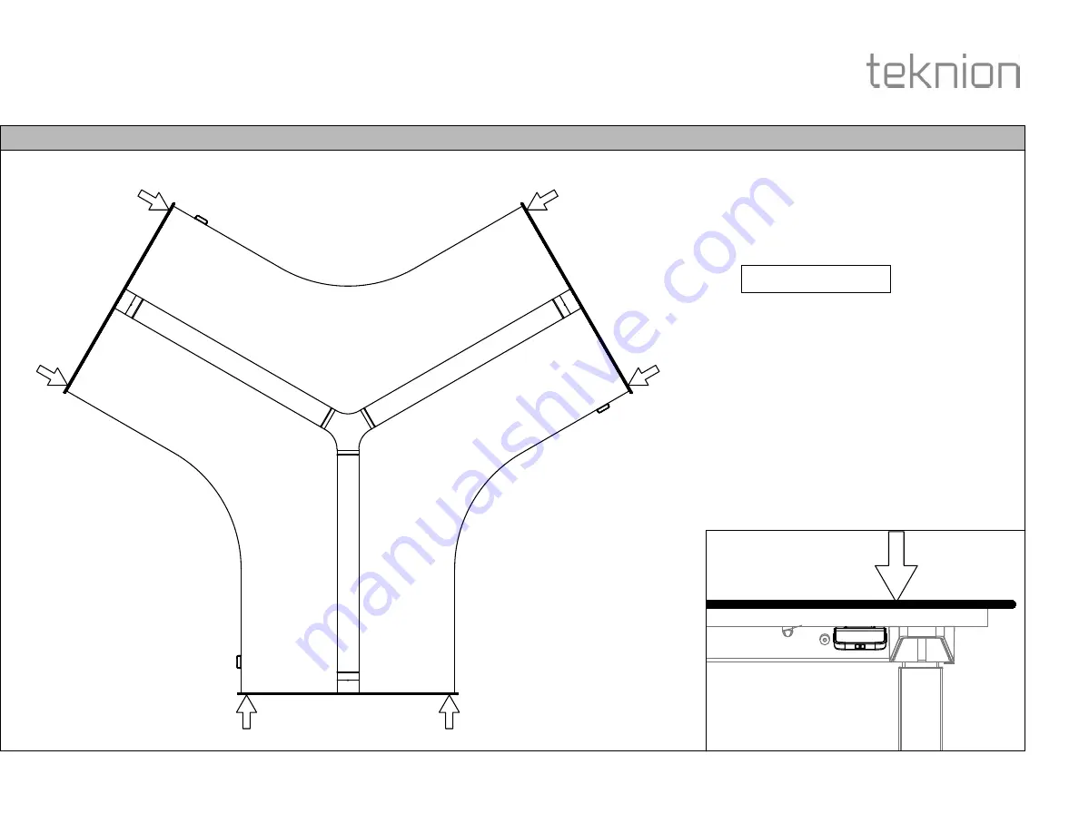
STEP 13: Align the Side edges and Top Surface with other Worksurfaces.

NOTE: Align Top and Side
edges of all Worksurfaces.

Содержание Navigate 120 HA Frame HNBFNT

Страница 1: ...and Navigate 120 Worksurface HNBWTN Section Description Page No Date Rev No 1 120 HA FRAME FRAMES AND WORKSURFACES May 2022 1 of 18 HABN_123 height adjustable bench Installation Guides B A8 A9 A6 A9 A5 A7 A4 A10 A3 A1 A10 A10 A2 A4 ...

Страница 2: ...ntegrated Power Bar w IEC N09 8737 x1 A12c Power Bar Hole Cover B02 0736 x1 OR OR A13a Motor Cable 500mm N09 8402 05 x3 OR A13b Motor Cable 1000mm N09 8402 10 x3 OR A13c Motor Cable 2000mm N09 8402 20 x3 OR OR A14 Navigate Digital Switch N09 8183 x1 A15 Navigate Simple Switch N09 8192 x1 A16 Display Switch w Up Down Memory N09 5600 x1 A17 Hardware Kit X05 0478 x1 A17a Screw 1 4 20x5 8 QD MCHN E01 ...

Страница 3: ... 120 HA FRAME FRAMES AND WORKSURFACES May 2022 3 of 18 HABN_123 height adjustable bench Installation Guides A18 Cable Felt Organizer YEYA01 x1 A19 Plastic Tray Cable Management w IEC N09 9781 x1 A20 Plastic Tray Cable Management YEYS01 x1 B Navigate 120 Worksurface HNBWTN x1 ...

Страница 4: ...d STEP 1 Adjust the Leveller to have a 0 5 Gap on all the Legs Section Description Page No Date LEVELLER ADJUSTMENT ASSEMBLE LEG AND MID GABLE STRATCHER HABN_123 4 of 18 May 2022 120 HA FRAME FRAMES AND WORKSURFACES height adjustable bench Installation Guides 0 5 Hanger Plate NOTE For Mid Gable assembly refer to HABN_224b A6 A2 A5 A2 A1 A17c ...

Страница 5: ...ews and washers provided Section Description Page No Date ATTACH POWER POLE MOUNT OPTIONAL ASSEMBLE CENTRE LEG TOP MOUNT HABN_123 5 of 18 May 2022 120 HA FRAME FRAMES AND WORKSURFACES height adjustable bench Installation Guides NOTE For Power Pole assembly refer to HABN_324 A3 Power Pole Mount A17b A3 A3 A17b ...

Страница 6: ...o Date INSTALL CROSS BEAM May 2022 6 of 18 HABN_123 120 HA FRAME FRAMES AND WORKSURFACES height adjustable bench Installation Guides STEP 5 Place Cross Beam as shown Secure the cross beam using the Screws provided A4 A3 A3 A17b ...

Страница 7: ...L LEG ASSEMBLIES May 2022 7 of 18 HABN_123 120 HA FRAME FRAMES AND WORKSURFACES height adjustable bench Installation Guides STEP 6 Place Cross Beam into the cross beam Secure the Leg assemblies using the screws provided A17b A6 A5 A5 A6 A17b ...

Страница 8: ...STRETCHER WELDMENT May 2022 8 of 18 HABN_123 120 HA FRAME FRAMES AND WORKSURFACES height adjustable bench Installation Guides STEP 7 Align Stretcher Weldment as as shown above Assemble Stretcher weldment with screws provided A7 A7 A7 A17c A17c ...

Страница 9: ...ring the legs into the same horizontal plane determined with the self leveling laser leveler before proceeding to the next step Refer to Step 1 to adjust levelers NOTE Use Laser Mark tool to check alignment NOTE The Unit must be leveled at the exact location of use If moved after installation or initial leveling follow Step 1 and Re align according to the floor profile Laser Mark ...

Страница 10: ...e ATTACH STRUTS TO FRAME May 2022 10 of 18 HABN_123 120 HA FRAME FRAMES AND WORKSURFACES height adjustable bench Installation Guides STEP 8 Attach the Struts to the Leg assemblies and Secure it using the Screws provided A8 A8 A8 A17b ...

Страница 11: ...e No Date ATTACH STRUT COVERS May 2022 11 of 18 HABN_123 120 HA FRAME FRAMES AND WORKSURFACES height adjustable bench Installation Guides STEP 9 Attach the Strut Covers and Secure it using the Screws provided A9 A9 A9 A9 A17b ...

Страница 12: ...STEP 10a Attach Power Module as shown above and Secure using the Screws provided Section Description Page No Date POWER MODULE OPTIONAL POWER MODULE COVER OPTIONAL HABN_123 12 of 18 May 2022 120 HA FRAME FRAMES AND WORKSURFACES height adjustable bench Installation Guides OR A12a A12b A12c ...

Страница 13: ...ch Installation Guides STEP 11 Connect all Wire as shown above NOTE Plug IEC Connector from item A12a into item A11 to power the actuator NOTE Plug IEC Connector from item A12a into item A11 to power the actuator A12a A17i A13c A13b A13c A13b A13a A11 A12a A14 A12a Dongle NOTE Make sure that the Dongle is connected to the Control Box ...

Страница 14: ...E FRAMES AND WORKSURFACES height adjustable bench Installation Guides STEP 12 Place Worksurface on the Frame assembly and Fasten with Screws provided Place the Switch under the Worksurface and Fasten with Screws provided A17a A17l NOTE The Power Module wire has been Hidden for Illustration Purpose ...

Страница 15: ...ACE AND SWITCH 2 May 2022 15 of 18 HABN_123 120 HA FRAME FRAMES AND WORKSURFACES height adjustable bench Installation Guides STEP 13 Align the Side edges and Top Surface with other Worksurfaces NOTE Align Top and Side edges of all Worksurfaces ...

Страница 16: ... AND SWITCH 3 May 2022 16 of 18 HABN_123 120 HA FRAME FRAMES AND WORKSURFACES height adjustable bench Installation Guides STEP 14 Fasten Worksurfaces with the Frame assembly A17m NOTE The Power Module wire has been Hidden for Illustration Purpose ...

Страница 17: ...120 HA FRAME FRAMES AND WORKSURFACES height adjustable bench Installation Guides STEP 15 Secure the Control Box to the Worksurfaces using the Screws provided Then Attach the Control Box cover to the Cross Beam A17f A10 NOTE The Power Module wire has been Hidden for Illustration Purpose ...

Страница 18: ...tion Description Page No Date ATTACH FELT COVER CABLE ORGANIZER ATTACH DUAL PLASTIC TRAY CABLE MANAGEMENT HABN_123 18 of 18 May 2022 120 HA FRAME FRAMES AND WORKSURFACES height adjustable bench Installation Guides NOTE If YEYA is specified refer to Complement Guide COM_151a NOTE If YEYS is specified refer to Complement Guide COM_151b ...

Отзывы: