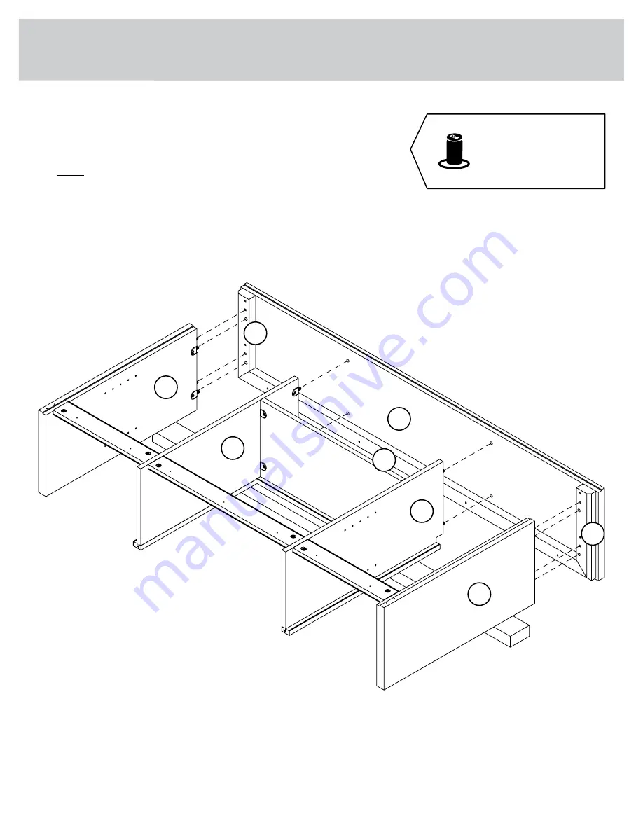
Teknik 5427027 Скачать руководство пользователя страница 15

Step 10

 å

Fasten the MOLDINGS (D and E) and TOP (P) to the

ENDS (A and B) and UPRIGHTS (C and Q). Tighten eight 

TWIST-LOCK® FASTENERS.

 å

NOTE: Be sure the WOOD DOWELS in the ENDS and

UPRIGHTS insert into the MOLDINGS and TOP.

P

A

B

C

Q

D

M

E

Page 15

Now might be a  

good time to refresh 

your drink.

Содержание 5427027

Страница 1: ...S INSTRUCTION BOOKLET CONTAINS IMPORTANT SAFETY INFORMATION PLEASE READ AND KEEP FOR FUTURE REFERENCE Prime Oak Hutch Model 5427027 Knick knack paddywhack give your stuff a home Teknik www teknikoffic...

Страница 2: ...ication Hardware Usage Guide Assembly Steps Fran ais Espa ol Safety Warranty 3 4 5 6 22 23 25 26 28 29 30 31 Page 2 No 2 Phillips Screwdriver Tip Shown Actual Size Hammer Not actual size Nail Holder p...

Страница 3: ...dentify similar parts Now you know our ABCs A RIGHT END 1 B LEFT END 1 C LEFT UPRIGHT 1 D RIGHT TOP MOLDING 1 E LEFT TOP MOLDING 1 F FIXED SHELF 1 G LEFT ADJUSTABLE SHELF 1 H FIXED SHELF MOLDING 1 J A...

Страница 4: ...1S BROWN 1 5 8 FLAT HEAD SCREW 8 55S MOLDING CONNECTOR 2 17F CAM SCREW 6 8F WOOD DOWEL 4 15F HIDDEN CAM 6 1F SILVER 1 LARGE HEAD SCREW 8 102S BRACKET CONNECTOR 2 81G NAIL 21 1N CLIP 7 67G 37F TWIST L...

Страница 5: ...river as tight as possible Dowel end 2 Push a TWIST LOCK FASTENER into the large hole in the part 1 HOW TO USE A TWIST LOCK FASTENER Cam Screw Hidden Cam Arrow Push a HIDDEN CAM into the part The arro...

Страница 6: ...les in the ENDS A and B UPRIGHTS C and Q and FIXED SHELF F A B C F Q 37F Do not tighten the TWIST LOCK FASTENERS in this step 37F Meet Parts A and B These components have been engineered to be lighter...

Страница 7: ...Turn six CAM SCREWS 8F into the ENDS A and B and UPRIGHTS C and Q Insert four WOOD DOWELS 15F into the ENDS A and B Step 2 A B C Q 8F 8F 8F 15F Page 7...

Страница 8: ...499 886 Step 3 F C Q H K K Slide the UPRIGHT MOLDING K onto the notched edge These surfaces should be even Notched edge Notched edge Notched edge The groove is closer to this edge These surfaces shou...

Страница 9: ...Push six HIDDEN CAMS 1F into the BRACES L and N Step 4 L N N 1F Arrow 1F Arrow Page 9...

Страница 10: ...D SHELF F and LONG BRACE L Tighten four TWIST LOCK FASTENERS and two HIDDEN CAMS Step 5 L F H C Q Surface with HIDDEN CAMS Surface with TWIST LOCK FASTENERS Surface with TWIST LOCK FASTENERS Surface w...

Страница 11: ...Fasten the SHORT BRACES N to the UPRIGHTS C and Q Tighten two HIDDEN CAMS Step 6 C Q N N Surface with HIDDEN CAMS Surface with HIDDEN CAMS Curved edge Curved edge Page 11...

Страница 12: ...Fasten the ENDS A and B to the SHORT BRACES N Tighten two HIDDEN CAMS Step 7 Surface without TWIST LOCK FASTENERS Surface with TWIST LOCK FASTENERS A B N N Page 12 Notched edge Notched edge...

Страница 13: ...ONNECTORS 17F into the notches in the MOLDINGS D E and M Flat end 17F Unfinished surface D E M Use your hammer to tap the MOLDING CONNECTORS 17F into the notches in the MOLDINGS Page 13 Unfinished sur...

Страница 14: ...5S NOTE Start each SCREW a few turns before completely tightening any of them NOTE Do not overtighten the SCREWS into the TOP Step 9 M D E Surface with holes Notched edge P BROWN 1 5 8 FLAT HEAD SCREW...

Страница 15: ...TOP P to the ENDS A and B and UPRIGHTS C and Q Tighten eight TWIST LOCK FASTENERS NOTE Be sure the WOOD DOWELS in the ENDS and UPRIGHTS insert into the MOLDINGS and TOP P A B C Q D M E Page 15 Now mig...

Страница 16: ...to lower edge of the LEFT END Remove the Nail Holder from the NAIL and completely tap the NAIL in with your hammer Finish fastening the BACK to the LEFT END with the hammer and Nail Holder placing NAI...

Страница 17: ...of the BACK and the teeth of the CLIPS should bite into the BRACES as you tighten the screws Follow diagram 1 Fasten the BRACKET CONNECTORS to the ENDS A and B Use four SILVER 1 LARGE HEAD SCREWS 102...

Страница 18: ...fasten the SAFETY STRAP to the TOP P There is no pre drilled hole With extra force use the short screw provided NOTE Position the SAFETY STRAP hole by measuring 2 in from the back edge of the TOP Step...

Страница 19: ...s through the open holes in the BRACKET CONNECTORS 81G Fasten the HUTCH to the unit you have drilled the holes into Use four SILVER 1 LARGE HEAD SCREWS 102S through the BRACKET CONNECTORS and into the...

Страница 20: ...hillips screwdriver or a hand drill press the screw slightly onto the drywall 3 Apply pressure turn the screw until a pilot hole is made and the nylon sheath slips through 4 Turn the screw until it is...

Страница 21: ...he RIGHT ADJUSTABLE SHELF R Insert the SHELF RESTS 10R into the hole locations of your choice in the ENDS A and B and UPRIGHTS C and Q Set the ADJUSTABLE SHELVES G and R onto the SHELF RESTS Step 16 G...

Страница 22: ...ER 105P or TWIST LOCK FASTENER COVER 112P onto each visible TWIST LOCK FASTENER NOTE Please read the back pages of the instruction booklet for important safety information This completes assembly Clea...

Страница 23: ...should be removed from the desktop before attempting to move the desk Do not push furniture especially on a carpeted floor Have a friend help you lift the item and set it in place This unit must be p...

Отзывы: