Teknik 5426135 Скачать руководство пользователя страница 7

Step 1

 å

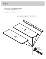
Assemble your unit on a carpeted fl oor or on the empty
carton to avoid scratching your unit or the fl oor.

 å

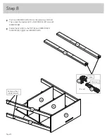
Push fi ve HIDDEN CAMS (1F) into the UPPER BACKS (P)
and a UPPER LEG (E). Then, insert the metal end of a 
CAM DOWEL (2F) into each HIDDEN CAM.

Do not tighten the HIDDEN CAMS in this step.

Arrow

1F

2F

(5 used)

Metal end

P

P

E

Page 7

Содержание 5426135

Страница 1: ...TE THIS INSTRUCTION BOOKLET CONTAINS IMPORTANT SAFETY INFORMATION PLEASE READ AND KEEP FOR FUTURE REFERENCE Home Study 3 Shelf Bookcase Model 5426135 The stories of your life Teknik www teknikoffice co uk ...

Страница 2: ...Table of Contents Assembly Tools Required Part Identification Hardware Identification Assembly Steps Hammer Not actual size No 2 Phillips Screwdriver Tip Shown Actual Size 3 4 5 6 32 Page 2 ...

Страница 3: ...SHELF 2 N ADJUSTABLE SHELF 1 O BOTTOM MOLDING 1 P UPPER BACK 2 Q LOWER FIXED SHELF 1 R DOOR 2 S LOWER BACK 1 A A B C D D E F G H J K L M N O P Q R R M K J L E E E P G F S Page 3 Part Identification å While not all parts are labeled some of the parts will have a label or an inked letter on the edge to help distinguish similar parts from each other Use this part identification to help identify similar...

Страница 4: ...URNITURE TIPPING RESTRAINT KIT 1 97 APPLIQUE CARD 5 100P WASHER 2 10I METAL PIN 4 1R CAM SCREW 12 8F PULL 2 22K DOOR STOP 2 4I WOOD DOWEL 6 15F NAIL 30 1N HIDDEN CAM 36 1F CAM DOWEL 24 2F RUBBER SLEEVE 4 2R 14H HINGE 4 Page 4 ...

Страница 5: ...hown actual size You may receive extra hardware with your unit BROWN 1 1 2 FLAT HEAD SCREW 7 14S SILVER 1 4 MACHINE SCREW 2 61S BLACK 1 2 FLAT HEAD SCREW 8 11S BLACK 9 16 FLAT HEAD SCREW 12 32S BLACK 1 15 16 FLAT HEAD SCREW 12 113S Page 5 ...

Страница 6: ...y tighten Arrow Maximum 210 degrees HOW TO USE A HIDDEN CAM CAM DOWEL Hole Hidden Cam Cam Dowel 2 Hole Hidden Cam Cam Dowel Insert the metal end of the CAM DOWEL into the HIDDEN CAM Metal end Arrow 1 Push a HIDDEN CAM into the part The arrow in the HIDDEN CAM must point toward the hole in the edge of the board Cam Screw Hidden Cam Arrow Push a HIDDEN CAM into the part The arrow in the HIDDEN CAM m...

Страница 7: ...arton to avoid scratching your unit or the floor å Push five HIDDEN CAMS 1F into the UPPER BACKS P and a UPPER LEG E Then insert the metal end of a CAM DOWEL 2F into each HIDDEN CAM Do not tighten the HIDDEN CAMS in this step Arrow 1F 2F 5 used Metal end P P E Page 7 ...

Страница 8: ...o the UPPER BACKS P and LEG E Tighten the HIDDEN CAM in the LEG E å NOTE The HIDDEN CAMS in the UPPER BACKS will be tightened in a later step Step 2 P P E B B BLACK 9 16 LARGE HEAD SCREW 1 used for the SAFETY STRAP Safety strap 97 Surface without HIDDEN CAMS Surface without HIDDEN CAMS Surface with HIDDEN CAMS Do not stand the unit upright without the BACK fastened The unit may collapse Caution Pa...

Страница 9: ...DDEN CAMS 1F into a UPPER FIXED SHELF M Then insert the metal end of a CAM DOWEL 2F into each HIDDEN CAM Step 3 M Do not tighten the HIDDEN CAMS in this step 1F 2F Metal end Arrow 1F 2F Arrow 4 used Metal end Page 9 ...

Страница 10: ...å Fasten a UPPER FIXED SHELF M to the LEG E Tighten one HIDDEN CAM Step 4 M Surface without HIDDEN CAMS E Page 10 Just think The sooner you do this the sooner you do something else ...

Страница 11: ...å Push one HIDDEN CAM 1F into a LEG E Then insert the metal end of a CAM DOWEL 2F into each HIDDEN CAM Step 5 E Do not tighten the HIDDEN CAMS in this step Arrow 1F 2F 1 used Metal end Page 11 ...

Страница 12: ...å Fasten the LEG E to the TOP B and UPPER FIXED SHELF M Tighten two HIDDEN CAMS Step 6 E M B Surface with HIDDEN CAMS Page 12 ...

Страница 13: ...D SHELF M Then insert the metal end of a CAM DOWEL 2F into each HIDDEN CAM å Fasten the UPPER FIXED SHELF M to the LEGS E Tighten two HIDDEN CAMS Step 7 M E E M Surface without HIDDEN CAMS 1F 2F Arrow Metal end 1F 2F 4 used Metal end Arrow Page 13 ...

Страница 14: ...ng LEGS E Then insert the metal end of a CAM DOWEL 2F into each HIDDEN CAM å Fasten the LEGS E to the TOP B and UPPER FIXED SHELVES M Tighten six HIDDEN CAMS Step 8 E E Arrow 1F 2F 2 used Metal end B M M E E Surface without HIDDEN CAMS Page 14 ...

Страница 15: ...the LOWER FIXED SHELF Q to the LEGS E and UPPER BACKS P Use eight BLACK 1 15 16 FLAT HEAD SCREWS 113S Step 9 E E E E Q P P BLACK 1 15 16 FLAT HEAD SCREW 8 used in this step 113S Page 15 Surface with fewer holes ...

Страница 16: ...SHELF Q å Fasten the UPPER BACKS P to the UPPER FIXED SHELVES M Use four BLACK 1 15 16 FLAT HEAD SCREWS 113S å Peel APPLIQUES from the APPLIQUE CARDS 100P and stick them onto each visible HIDDEN CAM and SCREW head Step 10 P P Q 4I 20 used To cover HIDDEN CAMS To cover screws 100P Page 16 M M BLACK 1 15 16 FLAT HEAD SCREW 4 used in this step 113S ...

Страница 17: ...P B Use seven BROWN 1 1 2 FLAT HEAD SCREWS 14S å Peel APPLIQUES from the APPLIQUE CARDS 100P and stick them onto each visible SCREW head Step 11 B C D D BROWN 1 1 2 FLAT HEAD SCREW 7 used in this step 14S Page 17 100P To cover screws 7 used ...

Страница 18: ...OLDING comes up off of the SCREWS remove it and slide it on again å Slide the MOLDING L onto the END A until it comes into contact with the MOLDING K å NOTE If the MOLDING comes up off of the SCREWS remove it and slide it on again å Repeat this step for the remaining END Step 12 A L K BLACK 9 16 FLAT HEAD SCREW 12 used in this step 32S Apply pressure with your hands as you guide the MOLDING over t...

Страница 19: ...MOLDING should be even on both edges of the END å NOTE If the MOLDING comes up off of the SCREWS remove it and slide it on again å Repeat this step for the remaining END Step 13 J A Apply pressure with your hands as you guide the MOLDING over the SCREWS and onto the END Page 19 Now might be a good time to refresh your drink ...

Страница 20: ...å Push eight HIDDEN CAMS 1F into a END A å Repeat this step for the remaining END Step 14 1F Arrow 1F Arrow 1F Arrow A Page 20 ...

Страница 21: ...å Turn six CAM SCREWS 8F into the LEGS F and G å Insert two WOOD DOWELS 15F into the LEGS F and G å Repeat this step for the remaining LEGS Step 15 G F 8F 8F 15F Page 21 ...

Страница 22: ... to the END A Tighten six HIDDEN CAMS å NOTE Be sure the WOOD DOWELS in the LEGS insert into the END å Repeat this step for the remaining END Step 16 A G F These surfaces should be even The LEGS will overhang this edge Page 22 ...

Страница 23: ...he metal end of a CAM DOWEL 2F into each HIDDEN CAM on the short edges of the ENDS A å Fasten the ENDS A to the LOWER FIXED SHELF Q Tighten four HIDDEN CAMS Step 17 A A Surface with HIDDEN CAMS Surface without HIDDEN CAMS 2F Metal end 2F Metal end Q Page 23 ...

Страница 24: ...lide the BOTTOM MOLDING O onto the notched edge of the BOTTOM H å U S Patent No 5 499 886 Step 18 H H O 15F Slide the BOTTOM MOLDING O onto the notched edge These surfaces should be even Notched edge The groove is closer to this edge Surface with HIDDEN CAMS Do not tighten the HIDDEN CAMS in this step 1F 2F 4 used Metal end Arrow 1F 2F Arrow Metal end Page 24 ...

Страница 25: ...å Fasten the BOTTOM H to the ENDS A Tighten four HIDDEN CAMS Step 19 Surface with HIDDEN CAMS O H A A Page 25 ...

Страница 26: ...e LARGE BACK S and bottom surface of the BOTTOM H should be even Push on opposite corners of your unit if needed to make it square å Fasten the LOWER BACK S to your unit using the NAILS 1N Step 20 S NAIL 30 used in this step 1N Do not stand the unit upright without the BACK fastened The unit may collapse Caution Finished surface H Page 26 ...

Страница 27: ... and the end of the SAFETY STRAP 2 Using a Phillips screwdriver or a hand drill press the screw slightly onto the drywall 3 Apply pressure turn the screw until a pilot hole is made and the nylon sheath slips through 4 Turn the screw until it is flush against the wall and you feel a firm resistance 5 Continue to turn until the screw starts spinning freely å NOTE Before moving your unit to a different...

Страница 28: ...S 2R over the METAL PINS 1R Insert the METAL PINS into the hole locations of your choice in the ENDS A Set the ADJUSTABLE SHELF N onto the METAL PINS Step 22 4 used 2R 1R A A N Page 28 Hey It s starting to look like something ...

Страница 29: ...å Fasten two HINGES 14H to a DOOR R Use four BLACK 1 2 FLAT HEAD SCREWS 11S å Repeat this step for the remaining door Step 23 R 14H BLACK 1 2 FLAT HEAD SCREW 8 used in this step 11S Page 29 ...

Страница 30: ...the DOOR R to the END A as shown in the lower diagram Use the screws in the HINGES You should start each SCREW a few turns before completely tightening any of them å Fasten a PULL 22K to the DOOR R Use a WASHER 10I and a SILVER 1 4 MACHINE SCREW 61S å Repeat this step for the other DOOR R å See the next step for DOOR adjustments Step 24 A R Mounting screw Stop Hinge 10I 22K SILVER 1 4 MACHINE SCRE...

Страница 31: ...g screw in or out å To adjust the DOORS up and down vertical loosen both vertical adjustment screws Move the DOORS up or down to the desired location Tighten the screws after making adjustments å To adjust the DOORS in or out depth loosen the mounting screw one turn and move the DOORS in or out as needed Tighten the mounting screw after making adjustments Step 25 vertical adjustment Adjusting scre...

Страница 32: ...each visible HIDDEN CAM å NOTE Please read the back pages of the instruction booklet for important safety information å This completes assembly Clean with a damp cloth Wipe dry Step 26 4 used To cover HIDDEN CAMS 100P 35 lbs 35 lbs 35 lbs 25 lbs 50 lbs No load Page 32 ...

Страница 33: ... break if improperly moved Physical injury Furniture can be very heavy Unload shelves from top to bottom before moving the furniture Do not push furniture especially on a carpeted floor Have a friend help you lift the item and set it in place This unit must be positioned against a wall Children climbing on the shelves can cause the product to tip Risk of injury or death Do not allow children to cli...

Отзывы: