background image

Step 16


å

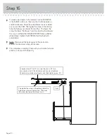
To make adjustments to the drawers, loosen SCREW #3
in the SLIDES a 1/4 turn, then turn the CAM clockwise or 
counter-clockwise. Notice how the drawer raises or lowers 
as you turn the CAM. The higher the screw in the oblong 
hole, the higher your drawer front will be.  The lower the 
screw, the lower the drawer front. By adjusting the drawers 
this way, it will help the DRAWER FRONTS line up better 
when closed. Tighten the SCREW when fi nished with 
adjustments.


å

NOTE: Please read the back pages of the instruction
booklet for important safety information.


å

This completes assembly. Clean with your favorite furniture
polish or a damp cloth. Wipe dry.

Cam

The higher the screw in the oblong hole, the 
higher your drawer front will be. The lower 
the screw, the lower the drawer front.

Loosen screw #3 a 1/4 turn, turn the cam a 1/4 turn 
maximum in both the clockwise and counter-clockwise 
directions to make adjustments, and then tighten screw #3.

Page 20

Содержание 5401562

Страница 1: ...Sit and surf NOTE THIS INSTRUCTION BOOKLET CONTAINS IMPORTANT SAFETY INFORMATION PLEASE READ AND KEEP FOR FUTURE REFERENCE Computer Workcentre 5401562 Teknik www teknikoffice co uk ...

Страница 2: ...wn Actual Size Skip the power trip This time 2 3 3 4 5 16 21 24 25 28 29 30 31 Part Identification A RIGHT END 1 B LEFT END 1 C UPRIGHT 1 D TOP 1 D28 RIGHT DRAWER SIDE 2 D29 LEFT DRAWER SIDE 2 D78 DRAWER BACK 2 D707 DRAWER BOTTOM 2 E MODESTY PANEL 1 F BACK 1 G BRACE 1 H KEYBORAD SHELF 1 I KEYBOARD FRONT 1 J KEYBOARD BACK 1 K KEYBOARD SIDE 2 L DRAWER FRONT 2 Q END MOLDING 1 R BASE 1 Page 2 ...

Страница 3: ...se this part identification to help identify similar parts Now you know our ABCs Part Identification A B C D E F G H I J K K L L R D28 D28 D29 D29 D78 D78 D707 D707 Hardware Identification 35GA CABINET RIGHT 2 35GB CABINET LEFT 2 35GC DRAWER RIGHT 2 35GD DRAWER LEFT 2 35AW CABINET RIGHT 1 35AY DRAWER RIGHT 1 35AZ DRAWER LEFT 1 35AX CABINET LEFT 1 Q Page 3 ...

Страница 4: ...HEAD SCREW 6 PP SS SILVER 5 8 MACHINE SCREW 6 BROWN 7 16 LARGE HEAD SCREW 8 VV BLACK 1 7 8 FLAT HEAD SCREW 2 OO RR BROWN 1 FLAT HEAD SCREW 4 HINGE 2 GG EXTENSION BRACKET 2 EE BLACK 1 1 16 MACHINE SCREW 1 QQ WW GOLD 5 16 FLAT HEAD SCREW 20 CATCH 1 HH LATCH 1 II METAL PIN 3 NN BARREL NUT 1 JJ MM SLIDE CAM 4 PULL MOUNT 6 KK PULL 3 LL NAIL 15 XX 30S BLACK 1 9 16 FLAT HEAD SCREW 8 HIDDEN CAM 10 BB2 CAM...

Страница 5: ...or the floor å Push ten HIDDEN CAMS BB2 into the ENDS A and B UPRIGHT C MODESTY PANEL E and BRACE G Then insert a CAM DOWEL CC2 into each HIDDEN CAM 10 used 10 used Arrow Do not tighten the HIDDEN CAMS in this step Insert the metal end of the CAM DOWEL into the HIDDEN CAM Arrow A B C E G CC2 BB2 Page 5 ...

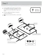
Страница 6: ...HT 35AW to the opposite surface of the UPRIGHT C å NOTE Be sure the roller end of each RAIL is at the same end 1 1 1 1 2 2 2 2 3 3 3 3 Roller end Roller end GOLD 5 16 FLAT HEAD SCREW 10 used in this step WW These holes must be here These holes must be here S u r f a c e w i t h H I D D E N C A M S S u r f a c e w i t h H I D D E N C A M S A C Remember Righty tighty Lefty loosey Page 6 ...

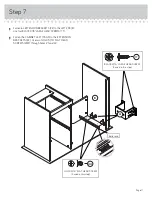
Страница 7: ... the END MOLDING Q to the LEFT END B Use three BLACK 9 16 LARGE HEAD SCREWS TT å NOTE There are no pre drilled holes in the END MOLDING Q Turn the screws into the groove of the END MOLDING Do not over tighten BLACK 9 16 LARGE HEAD SCREW 10 used in this step TT 7 used DD DD A C B Q Groove Page 7 S u r f a c e w i t h H I D D E N C A M S S u r f a c e w i t h H I D D E N C A M S S u r f a c e w i t ...

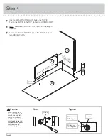
Страница 8: ...å Fasten the MODESTY PANEL E to the END B Tighten two HIDDEN CAMS Start Tighten Arrow Minimum 190 degrees Caution Risk of damage or injury HIDDEN CAMS must be completely tightened HIDDEN CAMS that are not completely tightened may loosen and parts may separate To completely tighten Arrow Maximum 210 degrees B D E Notch Surface with HIDDEN CAMS Surface with HIDDEN CAMS NN Page 8 ...

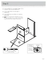
Страница 9: ...RIGHT C Tighten one HIDDEN CAM å NOTE Be sure the METAL PIN in the BRACE inserts into the hole in the UPRIGHT You may need to hold the BRACE up until the RIGHT END is fastened in the next step Step 5 E Surface with HIDDEN CAMS S u r f a c e w i t h H I D D E N C A M S C BLACK 1 7 8 FLAT HEAD SCREW 2 used in this step OO Arrow Minimum 190 degrees Maximum 210 degrees G Page 9 D ...

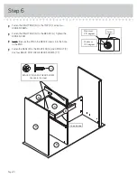
Страница 10: ...the HIDDEN CAM å NOTE Be sure the PIN in the BRACE inserts into the hole in the END å Fasten the BASE R to the RIGHT END A and UPRIGHT C Use four BLACK 9 16 LARGE HEAD SCREWS TT Step 6 Arrow Minimum 190 degrees Maximum 210 degrees A G R C Curved edge BLACK 9 16 LARGE HEAD SCREW 4 used in this step TT Page 10 D ...

Страница 11: ...LARGE HEAD SCREWS TT å Fasten the CABINET LEFT 35AX to the EXTENSION BRACKETS EE Use two GOLD 5 16 FLAT HEAD SCREWS WW through holes 1 and 2 Step 7 BLACK 9 16 LARGE HEAD SCREW 4 used in this step TT EE GOLD 5 16 FLAT HEAD SCREW 2 used in this step WW Roller end 1 2 B Page 11 ...

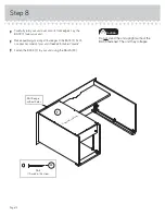
Страница 12: ...dges of the BACK F Push on opposite corners of your unit if needed to make it square å Fasten the BACK F to your unit using the NAILS XX Step 8 F F i n i s h e d s u r f a c e BACK edge without holes Do not stand the unit upright without the BACK fastened The unit may collapse Caution NAIL 15 used in this step XX Page 12 ...

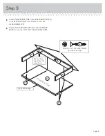
Страница 13: ... 1 1 4 FLAT HEAD SCREWS PP å Fasten the KEYBOARD SIDES K to the KEYBOARD BACK J Use two 1 1 4 FLAT HEAD SCREWS PP Step 9 H J K K These surfaces should have the same finish Long finished edge F i n i s h e d s u r f a c e BLACK 1 1 4 FLAT HEAD SCREW 6 used in this step PP PP PP Page 13 ...

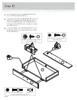
Страница 14: ...the BARREL NUT JJ onto the end of the SCREW Use two screwdrivers to tighten the SCREW and NUT å Fasten the HINGES GG to KEYBOARD SHELF H and KEYBOARD FRONT I Use eight BROWN 5 16 LARGE HEAD SCREWS VV Step 10 II HH GG BLACK 9 16 PAN HEAD SCREW 1 used in this step UU I I BROWN 7 16 LARGE HEAD SCREW 8 used in this step VV Page 14 H BLACK 1 1 16 MACHINE SCREW QQ JJ BARREL NUT 1 used of each to attach ...

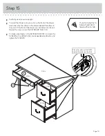
Страница 15: ...WER RIGHT 35AY and the DRAWER LEFT 35AZ to the KEYBOARD SHELF H Use four BROWN 1 FLAT HEAD SCREWS RR Roller end Roller end BROWN 1 FLAT HEAD SCREW 4 used in this step RR H Side Step Make nachos Optional but recommended Page 15 ...

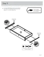
Страница 16: ...to the grooves in the DRAWER SIDES D28 and D29 and DRAWER FRONT L The tabs should insert freely into the slots Gently tilt the DRAWER SIDES side to side until the tabs slip into the slots Groove Start each screw a few turns before completely tightening any of them BLACK 1 9 16 FLAT HEAD SCREW 8 used in this step 30S Be sure the DRAWER BOTTOM inserts into the DRAWER FRONT groove D28 D28 D28 L L Unfi...

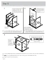
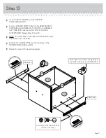
Страница 17: ...S WW through holes 1 and 3 å NOTE The screw head in the CAM must be visible through the slotted hole in the SLIDE å Push the FILE GLIDES 15B onto the top edges of the DRAWER SIDES D28 and D29 å Repeat this step for the remaining drawer Screw head turn CAM to line up holes in the SLIDES with holes in DRAWER SIDES MM MM Roller end Roller end 1 2 3 GOLD 5 16 FLAT HEAD SCREW 8 used in this step WW 15B...

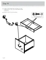
Страница 18: ...ULL MOUNTS KK and a PULL LL to each DRAWER FRONT I and L Use six SILVER 5 8 MACHINE SCREWS SS å Repeat this step for the remaining drawer Step 14 SILVER 5 8 MACHINE SCREW 6 used for the PULLS SS KK KK LL I L Page 18 ...

Страница 19: ...he rollers on the drawer behind the rollers on the unit Lift the front of the drawer up and slide it into the unit Repeat this step to insert the KEYBOARD SHELF H å To make adjustments to the KEYBOARD FRONT I loosen the SCREWS in the HINGES GG make needed adjustments and tighten the SCREWS Place the roller on the SLIDE behind the roller on the RAIL 25 lbs 70 lbs 25 lbs 25 lbs H GG I Page 19 ...

Страница 20: ...DRAWER FRONTS line up better when closed Tighten the SCREW when finished with adjustments å NOTE Please read the back pages of the instruction booklet for important safety information å This completes assembly Clean with your favorite furniture polish or a damp cloth Wipe dry Cam The higher the screw in the oblong hole the higher your drawer front will be The lower the screw the lower the drawer fr...

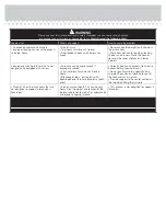
Страница 21: ...y moving furniture that is not designed and equipped with casters Furniture can tip over or break if improperly moved Physical injury Furniture can be very heavy Breakage of tops particularly with double pedestal furniture drawers at both ends Unload shelves and drawers from top to bottom before moving the unit Do not push furniture especially on a carpeted floor Have a friend help you lift the ite...

Отзывы: