


13
Floating Action Zones
• If a floating action actuating motor is connected to the terminals
Com 1-2 —1 —2 (19, 20 and 21), make sure power to the motor
circuit is off and install a jumper between the terminals
Com 1-2 — 1 (19 and 20). When the circuit is powered up, the valve should
start to open. If it does not, check the wiring between the terminal and the actuating motor and refer to any installation or
troubleshooting information supplied with the motor. If the valve closes instead of opening, the wiring to the actuating motor must
be reversed. If the valve opens correctly, turn off the power to the circuit and remove the jumper. Install a jumper between the
terminals
Com 1-2 — 2 (19 and 21). When the circuit is powered up, the valve should start to close. If it does not, check the wiring
between the terminal and the actuating motor and refer to any installation or troubleshooting information supplied with the motor.
If the valve closes correctly, turn off the power to the circuit and remove the jumper.
• If a floating action actuating motor is connected to the terminals
Com 3-4 —3 — 4 (22, 23 and 24), follow a similar procedure
to that described above.
• If a floating action actuating motor is connected to the terminals
Com 5-6 —5 —6 (25, 26 and 27), follow a similar procedure to
that described above.
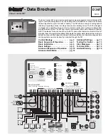
Advanced Settings
Design Outdoor
If the
Design Outdoor dial is turned up from the Off position the Demand Limiting function
is enabled. The
Design Outdoor dial determines the outdoor temperature at which full
heating output is required.
Floating Motor Speed
This dial is used to set the time required for the modulating valve to go from fully closed
to fully open.
Zone 2 Ventilating / Zone 2 Heating
If this DIP switch is set to
Zone 2 Ventilating, the 367 can operate a ventilation system
through output relay
2. If the DIP switches are set to Zone 1 Cooling and Zone 2
Ventilating, the 367 can operate a free cooling system through output relays 1 and 2. If
the DIP switch is set to
Zone 2 Heating the 367 operates output relay 2 as a heating zone.
Testing the Control Functions
STEP SEVEN
OPERATIONAL TEST OF CONTROL FUNCTIONS
The Zone Control 367 has a test routine which is used to test the main control functions. The 367 continually checks the sensors and
displays an error message whenever a fault is found. See page 15 for the list of error messages. When the
Test button is pushed, the
Test light is turned on. The Heat Required, and Optimum Start / Stop lights are turned off and the individual outputs and relays are tested
in the following test sequence.
Test Sequence
Each step in the test sequence lasts 10 seconds. At the end of each step, the device continues to operate
until it is turned off in a later step.
During the test routine, the test sequence can be paused by pressing the
Test button. The test sequence
remains paused at that point for up to 5 minutes. If the
Test button is not pressed again while the test
sequence is paused, the control exits the entire test routine. Once the test sequence is paused, the
Test
button can be pressed again to skip to the next step. This can also be used to rapidly skip through the test
sequence. To reach the desired step, repeatedly press and release the
Test button until the appropriate
device and indicator light turn on.
Step 1 - The System Pump relay is turned on.
Step 2 - If the Com 5-6 common block is used for a single One Stage zone, the control
turns on relay
5 for 10 seconds.
- If the
Com 5-6 common block is used for two One Stage zones, the control turns
on relay
5 for 10 seconds and then turns off relay 5 and turns on relay 6 for
10 seconds.
- If the
Com 5-6 common block is used for a Two Stage zone, the control turns
on relay
5 and then, after 10 seconds, turns on relay 6.
- If the
Com 5-6 common block is used for a Floating zone, the control turns on
relay
5 for 10 seconds and then turns off relay 5 and turns on relay 6 for
10 seconds.
- If an RTU is not connected to
RTU 5 or RTU 6 , the control skips this step.
1
2
1
System Pump
5
Zone 5 / Lo stage /
Open
Zone 6 / Hi stage /
Close
6
4
Zone 4 / Hi stage /
Close
3
Zone 3 / Lo stage /
Open
2
Zone 2 / Hi stage /
Close / Ventilation
Zone 1 / Lo stage /
Open / Cooling
1
System Pump
Test
Zone 1 Cooling
Zone 2 Ventilating
Floating Motor
Speed
130 sec.
30
230
100
200
0
°
F
-40
Off
Design Outdoor
30