1
98-05243-ENUS R2
Matrix
®
Pro
Copyrights
© 2013 TeeJet Technologies. All rights reserved. No part of this
document or the computer programs described in it may be
reproduced, copied, photocopied, translated, or reduced in any form or
by any means, electronic or machine readable, recording or otherwise,
without prior written consent from TeeJet Technologies.
Trademarks
Unless otherwise noted, all other brand or product names are
trademarks or registered trademarks of their respective companies or
organizations.
Limitation of Liability
TEEJET TECHNOLOGIES PROVIDES THIS MATERIAL “AS IS”
WITHOUT WARRANTY OF ANY KIND, EITHER EXPRESSED OR
IMPLIED. NO COPYRIGHT LIABILITY OR PATENT IS ASSUMED. IN
NO EVENT SHALL TEEJET TECHNOLOGIES BE LIABLE FOR ANY
LOSS OF BUSINESS, LOSS OF PROFIT, LOSS OF USE OR DATA,
INTERRUPTION OF BUSINESS, OR FOR INDIRECT, SPECIAL,
INCIDENTAL, OR CONSEQUENTIAL DAMAGES OF ANY KIND,
EVEN IF TEEJET TECHNOLOGIES HAS BEEN ADVISED OF SUCH
DAMAGES ARISING FROM TEEJET TECHNOLOGIES SOFTWARE.
Safety Information
TeeJet Technologies is not responsible for damage or
physical harm caused by failure to adhere to the following
safety requirements.
As the operator of the vehicle, you are responsible for its safe
operation.
The BoomPilot is not designed to replace the vehicle’s operator.
Do not leave a vehicle while the BoomPilot is engaged.
Be sure that the area around the vehicle is clear of people and
obstacles before and during engagement.
The BoomPilot is designed to support and improve efficiency while
working in the field. The driver has full responsibility for the quality and
work related results.
Matrix Pro GS Software Version 3.x
All information on settings to configure BoomPilot can be found in the
Matrix Pro GS User Manual.
General Matrix
®
Pro inforMation
The Matrix Pro is used to configure the vehicle and its implements.
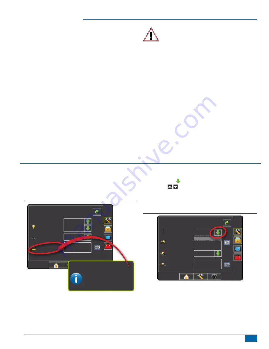
Setup Option Information
Press the option’s icon or option’s name of any menu item to display a
definition and range values of that item. To remove the information box,
press anywhere on the screen.
Figure 1-1: Example of Information Text Box
Config-> Lightbar
Brightness
Mode
LED Spacing
1.50 ft
Swath
50%
The distance illustrated by the
illuminated LED’s can be customized.
Input the desired spacing as required or
individual preference.
LED Spacing
Drop Down Menu Selections
Press DOWN arrow to access the list of options. Use the UP/
DOWN arrows or slide bar if necessary to scroll through the
extended list. Select the appropriate option. To close the list without
selecting an option, press anywhere on the screen outside the drop
down menu.
Figure 1-2: Example of Drop Down Menu
Config-> Vehicle
12.50 ft
0.00 ft
Backward
Vehicle Type
Ant Height
Dir to Boom
Dist to Boom
Front Wheel
Front Wheel
Articulated
Tracked


