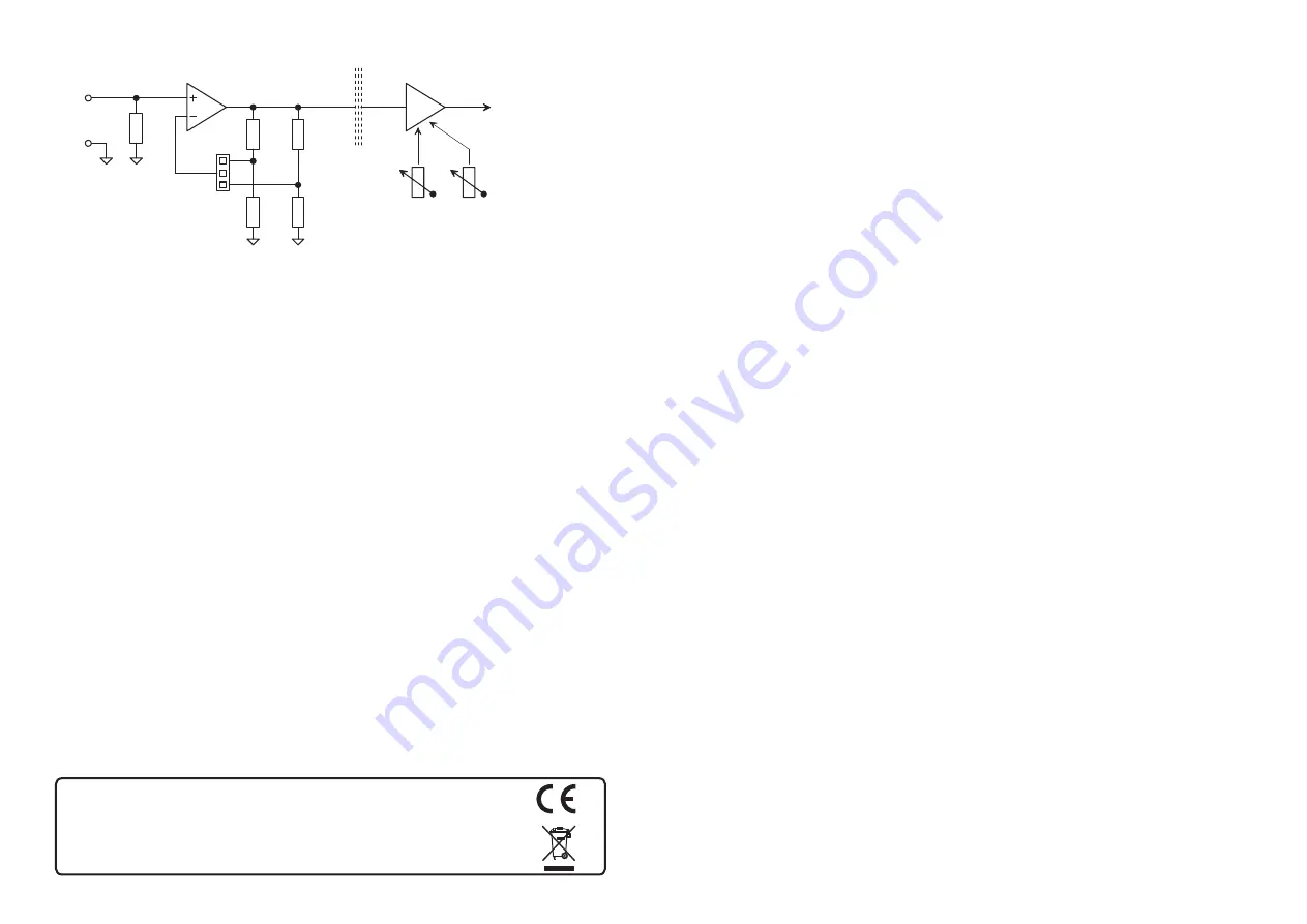
Fig. 1. Simplified schematic of OPT-1x20 internal circuits.
As you can find out from the schematic...
• the analog input can be equipped with a current shunt, or the input impedance
can be reduced by replacing R1 (a resistor with value of 1 MOhm and tolerance
of 1% is fitted at the factory);
• the input amplifier is equipped with positions for two dividers determining the
gain; the first is reserved for users and the factory setting is 1x amplification
(i.e. a resistor with value of 0 Ohm is fitted in position R5 and position R6 is left
free), the second is factory fitted with a divider for 10x gain (18K and 2K
resistors with a tolerance of 0.1%);
• after changing the range (i.e. relocating the JP1 jumper position) it is
recommended to re-compensate the offset and calibrate the gain (see the meaning
of potentiometers P1 and P2).
Warning: The manufacturer is not liable for damage to the OPT-1x20 board or
other damage caused by additional installation or change of components.
to the DAQ card
input
gain
adjustment
1x
offset
P1
P2
1M0
- - -
R5 0R
2K0
18K
R7
R6
R8
R1
isolation
10x
1x
adjustment
range configuration
JP1
Manufacturing, sales office, service center and technical support:
TEDIA spol. s r. o.
Zabelska 12, 31200 Plzen, Czech Republic
phone/e-mail:
https://www.tedia.eu/contacts
address:
OPT-1020/1120
User Guide
(further information available at http://www.tedia.eu)
document revision: 02.2013, © 1994-2013 TEDIA
®
spol. s r. o.


