background image

58

I. TWO-STROKE MECHANICAL EN-

GINE PARTS

1. UNIBLOCK ENGINES

(AV520-600-750-125)

a)

INTRODUCTION

Fig. 1 shows the short block.
Fig. 2 shows an exploded view of the engine.
As may be seen the momoblock is compact (combined
crankcase and cylinder) and it is sealed in the upper part
by the shroud mounting base.
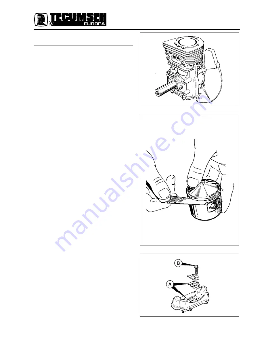
b)

EXTERNAL INSPECTION REED PLATE

Fig 3 shows the reed plate. In case of a broken or damaged
reed it is necessary to change the two reeds (

A

) by

removing the two screws (

B

).

NOTE

 - Use Loctite or similar for sealing when fitting

the two screws (

B

).

Fig. 1

Fig. 2

Fig. 3

www.mymowerparts.com

For  Discount Tecumseh Engine Parts Call 606-678-9623 or 606-561-4983

Содержание MV 100 S

Страница 1: ...ese numbers are stamped on the engine as shown below Always insist on genuine Tecumseh replacement parts ENGINE CODE SPECTRA 37 E 38000 SER 5 174 A MODELLO SPECIFICA NUMERO DI SERIE ANNO DI COSTR GIOR...

Страница 2: ...e the recommended ratio This gives increased protection during the piston ring seating process We also highly recommend the use of Tecumseh smokeless oil part number 26980003 which is an extremely hig...

Страница 3: ...lean fuel For 2 stroke engines AV and MV use a 4 25 1 or 2 50 1 petrol oil mixture Refer to the operator s manual for correct mix for each engine USE CLEAN FRESH FUEL FOR TESTING NOTE If engine is fit...

Страница 4: ...s NOTE Warm engine normally starts without choking Move control lever Fig 2 on engine or remote control Fig 2 on equipment to MAX position then follow b c and d instructions RECOIL STARTER PRIMER a Mo...

Страница 5: ...wise continue engine fault check ELECTRIC STARTER Fig 2 2 To start engine with electric start option follow the above procedure except use the key to activate the starter motor NOTE Ensure engine has...

Страница 6: ...gap setting electronic ignition NOTE When using the compression leak tester Fig 4 and the ignition tester Fig 5 faults may quickly be located If no fault can be found the defect must be within the ca...

Страница 7: ...oad ascertain that the equipment is disengaged if the unit has a heavy starting load Check remote control assy for proper adjustment with the lever A in choke or start position The carburettor choke s...

Страница 8: ...w Standard Top Starter 1 Retaining Screw 2 Retainer 3 Brake Spring 4 Dog 5 Dog Return Spring 6 Rope Pulley 7 Rewind Spring 8 Starter Housing 9 Rope 10 Handle To disassemble starter Release spring tens...

Страница 9: ...mbling starter always make sure that by pulling the rope slightly the starter dog operates and that the rope can be fully extended When released the handle should be held firmly against the starter ho...

Страница 10: ...plete with keeper in position and push spring into place in the container Fig 11 For further disassembly remove central fixing screw 3 and remove pulley assy Fig 12 Remove brake spring 10 and washer 8...

Страница 11: ...y the main spring and spindle must be greased Do not grease the brake spring etc in order to prevent the accumulation of dust Fault checking When the rope does not recoil check The spring hub 4 if thi...

Страница 12: ...entre pin by means of a drift and hammer The spring gear assy may now be removed Fig 2 Remove locking pin Fig 20 C and slowly release spring To replace Spring The new spring is supplied complete with...

Страница 13: ...to the body paying particular attention to position of the rope C and the brake spring M Fig 26 Fig 26 Correct assembly of rope C Rope passage M Spring brake Replace taper pin and remove locking pin C...

Страница 14: ...D SPRING IS NOT IN A CANISTER Care must be used when handling the pulley containing spring because the rewind spring and cover is held by the bosses in the cover Assembly procedure 1 Reverse the above...

Страница 15: ...ner 3 Pawls 4 Pawl Springs 5 Pulley 6 Spring 7 Cover 8 Housing 9 Rope 10 Handle NOTE Pulley 5 Spring 6 and Cover 7 are supplied as an assembly when purchased for spare parts purposes DISASSEMBLY REASS...

Страница 16: ...should be checked first Ensure that it is fully charged by recharging for 24 hours with charger supplied In low temperatures battery power reduces whilst power required to crank engine increases NOTE...

Страница 17: ...ternator has an output of 325 350 mA at 3000 rpm which is sufficient to keep the battery charged under normal working conditions Air gap setting Loosen all lamination screws turn flywheel so magnet is...

Страница 18: ...sticks on the shaft it should be washed in solvent to remove dirt and grease and dried thoroughly If damaged replace parts The unit is disassembled by removal of the two end cap screws the bendix gea...

Страница 19: ...that the starter pinion to flywheel ring gear mesh is checked on re assembly The correct mesh is 1 5 mm 1 16 between the head of the pinion gear tooth and the base of the flywheel gear tooth Correct a...

Страница 20: ...On electric start systems the starter is energized to start the engine On non electric start systems recoil starter rope must be pulled to start engine WIRING DIAGRAMS Electric Start Systems Fig 3 Al...

Страница 21: ...ER THE PERSONAL SAFETY AND OR PROPERTY OF YOURSELF AND OTHERS READ AND FOLLOW ALL INSTRUC TIONS DISCONNECT BATTERY FROM CIRCUIT BEFORE MAKING CHECK To perform a continuity check of the switch use a co...

Страница 22: ...ONAL IGNITION SYSTEM Internal coil LAV HBL AV MV REMOVAL OF FLYWHEEL NOT MV OR BH TYPE Remove air shroud complete with starter Fig 2 Remove flywheel nut and starter hub using strap wrench part number...

Страница 23: ...nts gap see table if adjustment is necessary loosen screw securing static point and reset using feeler gauge Clean contacts with fine emery or contact file Remove all traces of oil if oil is present i...

Страница 24: ...uring screw COIL INSPECTION Inspect coil for damage cracks bad insulation or signs of overheating Check all leads particularly at point of entry to coil Check coil efficiency on a tester with coil mou...

Страница 25: ...tic mass located on the outside of the flywheel Fig 17 B The technical advantages of this system are More consistent spark at low rpm Fixed timing Adjustable air gap set to 0 38 mm 015 BREAKER POINTS...

Страница 26: ...until this is obtained denoted by rule position against straight edge or scale on special tool Slacken stator securing bolts and turn until points are just about to open If a test light is not availa...

Страница 27: ...checks of the high tension lead and sparking plug SOLID STATE IGNITION OPERATION As the magnets in the flywheel rotate past the charge coil electrical energy is produced in the module This energy is...

Страница 28: ...plug Remove and inspect spark plug Replace spark plug if electrodes are pitted or burned or if the porcelain is damaged For replacement use Champion RJ17LM or RJ19 LM for Side Valve MV engines Champio...

Страница 29: ...143 1 32 3 64 BV 150 BV 153 FIXED FIXED BVR 150 0 635 1 143 1 32 3 64 BV 172 FIXED FIXED BVR 172 BV 173 0 635 1 143 1 32 3 64 The engines produced since 1984 are equipped with electronic ignition TOP...

Страница 30: ...V600 601 605 MV100 S 2 25 2 75 3 32 7 64 AV750 755 2 00 2 50 5 64 7 64 AV125 MV100 MV100 S ELECTRONIC ELECTRONIC PRODUCED IGNITION IGNITION SINCE 1986 TOP DEAD CENTRE DIRECTION OF ROTATION VIEWED FROM...

Страница 31: ...insufficient lubrication It is therefore important that operators observe the instructions on air cleaner maintenance Engine operation is impaired by an air cleaner in bad condition and no warranty i...

Страница 32: ...e always perfectly clean and should not show any moulding defects burrs otherwise carburation may be affected 3 POLYURETHANE AIR CLEANER WITH SNORKEL A snorkel type pre cleaner is available to meet th...

Страница 33: ...ly efficient when the oil is at the level indicated on the bottom of the container Fig 9 D Check oil level every five 5 hours If not to correct level refill container using a similar oil to that used...

Страница 34: ...hly Shake or tap the thick black filter E to remove any dirt or dust If the thin white filter F is oil soaked and or covered with dust replace it DO NOT OIL THE FILTERS Replace the thicker filter E in...

Страница 35: ...nd squeeze it lightly to obtain a uniform distribution of the lubricant throughout the element Clean inside of element housing before refitting filters Wash snorkel pipe from inside with a flow of wat...

Страница 36: ...gs to enter air intake 3 Remove the felt pad by sliding it off the paper cartridge 4 Check the paper cartridge condition and replace if dirty Clean carefully inside of filter base 5 Install the new fe...

Страница 37: ...tion 1 in the preceding section Then proceed as follows 1 Clean inside the body the foam support and the filter base 2 Saturate the new foam with two table spoons approx 20 ml of clean engine oil Sque...

Страница 38: ...ace if it is damaged or deformed FOAM REPLACEMENT To remove the foam from the body please follow instructions 1 and 2 in the preceding section Then proceed as follows 1 Clean inside the body and the f...

Страница 39: ...TER Check filter every 10 hours or more frequently if used in dry dusty conditions Do not attempt to clean or oil filter FOAM PRE FILTER if any Do not attempt to oil filter Clean every three 3 months...

Страница 40: ...or are as follows DIAPHRAGM CARBURETTOR Fig 1 A Choke B Idle C Intermediate speed D Full load Inlet of petrol to carburettor is controlled by needle P During operation of the engine this needle is lif...

Страница 41: ...nlet of petrol to the carburettor is controlled by needle P When the petrol level decreases the float G falls and consequently the needle allows petrol to flow in and restore the level Fig 2 www mymow...

Страница 42: ...l adjustment set main adjustment needle A to position that will give smoothest performance Final adjustment should range between one and one and a half turns open Run engine at idle speed and adjust i...

Страница 43: ...s point check visually the gasket and diaphragm The latter should be in good condition and not cracked or hardened Remove the valve assembly 18 19 20 21 with a hexagonal 5 32 spanner or with a slotted...

Страница 44: ...o clean the fine filter located in the elbow Refit elbow After tapping it in by about one third use some Loctite or other adhesive to ensure a petrol tight fit when the elbow is completely inserted Fi...

Страница 45: ...art Fixed jet primer start The carburettors may be found with fixed Fig 13 or adjustable Fig 14 jet Fixed jets do not only differ by their size 68 or 82 etc but also by the number of emulsion holes an...

Страница 46: ...place if damaged Check the carburettor body for damage obstructed passages or worn spindle bushes Clean out obstructed passages with clean compressed air Replace body if damaged Check that petrol has...

Страница 47: ...Pre starting Primer 5 times Do NOT use pre starting Primer to re start a warm engine which has stopped for a short period If the engine is used in cool weather conditions the primer can be used to for...

Страница 48: ...urettor Good valves are essential for dependable starting Burned valves poor seats or improper valve stem clearance result in poor starting which is then incorrectly diagnosed as a carburettor problem...

Страница 49: ...bad starting MAIN JET BOWL NUT Due to the different styles of primer carburettor there are different types of Bowl Nut Main Jet used These jet types are not interchangeable NOTE Always refer to the ma...

Страница 50: ...balance between the two forces giving the desired throttle opening a Variable control type Fig 2 The control lever L secured to the bracket Fig 1 may be moved between the choke position and the stop...

Страница 51: ...o increase the speed Turn the screw in an anti clockwise position to decrease the speed Fig 5 On AV and MV engines the governor spring must be fitted Fig 6 with the hooks inserted from the top The spr...

Страница 52: ...rough the crankcase and to this is connected a lever and spring which automatically adjusts the engine speed c OLEOMATIC GOVERNOR FOR HORIZONTAL ENGINES FIG 9 The governor spool A Fig 9 is pushed by t...

Страница 53: ...link B is mounted on the lever E at the second hole from the internal side and the lever V at the first hole from the external side Before mounting the carburettor insert the link C in the first hole...

Страница 54: ...rnor arm A has three holes at the top The throttle control rod T being fitted to the lower of the three Fig 12 There are nine alternative holes at the bottom of the arm The long control spring being f...

Страница 55: ...spring assy W onto the arm A and control lever L Fit assembly plate with screws G and fit complete assy to engine Fit arm A to clamp S with screw P leave screw slack and turn arm A anticlockwise and...

Страница 56: ...oles B Clamp C R H thread with straight cut head Fig 19 new type A Lever 6 holes B Clamp C L H thread with Phillips head e GOVERNOR PLATE FOR PRIMER CARBU RETTOR Because of the different configuration...

Страница 57: ...For the governor plate mounting proceed as follows Install the plate on the intake pipe Insert the two fixing screws Push the plate to the end of the slots towards the filter side Tighten the screws N...

Страница 58: ...and cylinder and it is sealed in the upper part by the shroud mounting base b EXTERNAL INSPECTION REED PLATE Fig 3 shows the reed plate In case of a broken or damaged reed it is necessary to change t...

Страница 59: ...aid of special tool Part No 670286 c INTERNAL INSPECTION If compression loss occurs after inspection of the seals and gaskets dismantle the short block as follows Remove cylinder head With the cylind...

Страница 60: ...wear is outside these limits Insert rings into bore about 15 mm from the top and check ring gap Fig 7 See table for wear limits Replace ring if the distance exceeds the table limits To replace the pi...

Страница 61: ...are matched Fig 12 Fit the crankshaft protecting the oil seal Fit the piston conrod assembly ensuring that hole in the piston pin boss is on the flywheel side opposite to the exhaust Place the cylinde...

Страница 62: ...he figure 1 stamped on both cylinder and piston Fig 14 shows location of these marks 2 MONO BLOCK ENGINES MV100S a GENERAL The MV100S is fitted with a ball bearing on both top and bottom main bearings...

Страница 63: ...removal is made easier as the flywheel holes are already threaded It is now necessary to screw the self threading screws up to at least one thread more than those already tapped c ENGINE BLOCK DISASS...

Страница 64: ...he crankshaft webbs when driving on new PTO bearing FIG 21 A Heat block as per above and refit the crankshaft f SHROUD BASE REASSEMBLY Assembly should be made only after expanding the base Place the g...

Страница 65: ...bushed bearing on the conrod Refer to previous instructions for disassembly and reassembly except the bushed conrod big end cap is fitted with two retaining screws and one piece lock tab On assy ensu...

Страница 66: ...638 0644 1 638 0644 Width of snap ring groove 1 664 0656 1 664 0656 0 100 00394 Axial clearance of snap ring 0 132 00520 0 051 00201 0 051 00201 in groove 0 082 00323 0 20 0078 0 152 0059 0 152 0059...

Страница 67: ...ake side 25 400 1 000 25 395 9998 25 017 9849 Crankshaft bearing seat diam 17 009 6694 17 009 6694 17 009 6694 flywheel side 17 001 6693 17 001 6693 17 001 6693 Ball Ball Ball bearings bearings bearin...

Страница 68: ...12 and flywheel 3350 3650 3850 0 30 0 40 012 016 Spark advance Electronic Electronic 0 55 022 Distance between spark plug electrodes 0 60 024 0 20 008 Distance between ring points 0 35 014 52 781 2 07...

Страница 69: ...ng Ball Ball flywheel side bearings bearings Cuscinetto di banco Ball Ball lato presa di potenza bearings bearings Piston pin diam No No 12 692 4996 Engine shaft axial clearance 12 697 4998 Roller Rol...

Страница 70: ...rope guide 8 32 x 9 1 67 2 26 0 17 0 23 15 20 X X fastening screws Reed plate to cylinder 10 24 x 15 6 18 6 77 0 63 0 69 55 60 X X X fastening screws Starter to conveyor 1 4 28 x 10 5 69 6 77 0 58 0...

Страница 71: ...at cylinder head remove and check for distortion or damage to sparking plug threads if necessary replace the head using a new gasket NOTE With the SIC compression tester checking can be done without d...

Страница 72: ...h is not less than 24 mm 15 16 Replace springs if necessary Remove all traces of grinding paste and refit valves in their correct position refit springs and securing caps Fig 6 Check the tappet cleara...

Страница 73: ...moving plugs H for horizontal shaft engine and plug V for vertical shaft Fig 9 At this point check crankshaft for main bearing wear and according to engine type proceed as follows a ENGINES LAV BV HS...

Страница 74: ...complete with bearing and seal All types remove crankcase cover bolts and withdraw cover With PTO end uppermost remove gasket dowel pins and oil pump vertical shaft engines camshaft and tappets mark t...

Страница 75: ...check that bearing conform to sizes given in table b CRANKCASE COVER Check the side cover or base plate for damage or distortion PTO side bearing Fig 15 On engines with ball bearing check the conditio...

Страница 76: ...ith horizontal crankshaft have an oil dipper C and a lubricating hole a Con Rod caps may be retained by one of the following methods Lock Nut D Fig 17 Bolt and Lock Tab Fig 18 Locking Bolt Fig 19 Alwa...

Страница 77: ...ovality should not exceed 0 15 mm 006 Refer to table for dimensions With a feeler gauge measure ring clearance in groove Fig 22 This should not exceed 0 15 mm 006 Insert rings into cylinder bore push...

Страница 78: ...ng on the engine type pistons may have an off set piston pin This must be fitted towards the magneto side Piston pin Remove retaining rings Fig 26 and withdraw pin from piston Fig 27 Check for wear or...

Страница 79: ...on release assy a pin b rocker arm c centrifugal weight d return spring Alternatively the centrifugal weight has a ramp on it which lifts the valve at cranking speed This ramp retracts at normal runni...

Страница 80: ...d governor is situated inside the crankcase and consists of three parts 1 Governor gear 2 Flyweights 3 Spool a shaft b retaining rings The unit is mounted on shaft a and is secured by two rings b Remo...

Страница 81: ...crankcase breather the body of which contains a small celeron valve Fig 35 Two body types are made identified by the position of the oil drain hole Fig 35 A Vertical type B Horizontal type Check that...

Страница 82: ...out the tube Condensed oil vapour returns to the crankcase by means of the oil return holes Some engines have the breather tubes connected to the air cleaner assembly The filter element can be cleane...

Страница 83: ...g end journal towards cylinder bore the crankshaft runs in a needle bearing flywheel side and ball bearing PTO side The flywheel side crankshaft main bearing journal is hardened for use with needle be...

Страница 84: ...ponents Fig 45 d PISTON AND RINGS Piston rings must be fitted with tapers upwards on compression rings and expander under the scraper rings Fig 46 On some engines LAV 172 HBP 40 BHG the second compres...

Страница 85: ...50 B Insert piston into bore from top lubricate and enter rings with the aid of a ring compressor tool push home until big end seats on crankshaft journal lubricate well and fit big end cap and dippe...

Страница 86: ...curing bolts in sequence to torque figures in table On engines with ball bearings Fit crankcase cover on crankshaft turning crankshaft to mesh governor gear Push fully home and fit bolts in sequence F...

Страница 87: ...same time ensuring that oil pump plunger is located in base plate Fitting external parts Position cylinder head and gasket on cylinder and insert head bolts Tighten as per torque figures given in tabl...

Страница 88: ...ews rocker arms and push rod guide plate Fig 60 The push rods can be removed from the engine and the cylinder head bolts can be removed to take the head off the engine Fig 61 The valve springs can be...

Страница 89: ...per steps to be taken to reassemble the valve train components into the engine After properly servicing the valves and valve seats if so required place the intake and exhaust valves into their proper...

Страница 90: ...he guide plate in position on the head the tabs on the guide plate face out Fig 69 1 Install the rocker arm and pivot ball screw with the lock nut on far enough to hold the guide plate in position The...

Страница 91: ...setting hold the Allen wrench on the pivot ball screw and tighten the lock nut to 65 85 inch pounds 6 5 8 5 Nm of torque Double check the setting to make sure that it did not change when the lock nut...

Страница 92: ...different degree cutters 88841013 First use the 31 degree cutter to clean and narrow the seat from the top toward the centre Fig 75 Second use the 46 degree cutter to cut in the seat to a width of 3 6...

Страница 93: ...learance mm 0 689 0 689 0 689 0 689 0 689 0 689 0 689 Piston skirt diamter mm 63 383 63 383 66 520 71 298 70 866 63 383 66 520 70 866 63 395 63 395 66 530 71 310 70 891 63 395 66 530 70 891 Distance b...

Страница 94: ...63 395 66 530 Distance between compression 0 178 0 178 Ring points mm 0 432 0 432 Crankshaft bearing diameter flywheel side Ball bearings Crankshaft bearing diameter power intake side Ball bearings I...

Страница 95: ...or engine starter 1 4 20 8 44 11 28 75 100 Viti fissaggio avviat later o motorino elettrico 1 4 20 9 02 10 10 80 90 Oil expansion pipe fastening screw self threading 10 32 1 67 2 84 15 25 Tank fasteni...

Страница 96: ...95 9 02 70 80 Screws for fastening carburettor to inlet pipe 1 4 28 6 18 7 95 55 70 Screws for fastening filter shell to carburettor 10 32 1 67 2 84 15 25 Silencer screws 1 4 20 8 44 10 10 75 90 Cylin...

Страница 97: ...T START OR HAS DIFFICULTY STARTING 1 1 1 4 1 7 2 4 2 5 2 6 3 1 3 4 4 1 4 2 4 3 4 4 4 5 5 1 5 2 5 6 5 7 5 8 ENGINE DOES NOT GIVE 1 2 2 5 2 8 5 2 5 3 ENGINE DOES NOT SHUT OFF 1 3 ENGINE IS HARD AT START...

Страница 98: ...already cut grass DEFECT 1 The starter throttle is not completely closed therefore the engine has difficulty in starting due to lack of fuel enrichment especially when cold 2 The MAX machine setting...

Страница 99: ...being dangerous for the operator will surely cause breakages not covered by warranty 7 During machine cleaning and maintenance operations avoid inverting the engine with head spark plug side facing do...

Страница 100: ...Once the fuel in the float chamber is consumed the engine stops By leaving the engine off for a few minutes the float chamber is able to fill up agaiin and the engine will start but the problem repea...

Страница 101: ...leaning Resetting DEFECT 7 Air may drawn in through the parts that connect with the carburettor air filter inlet manifold check tightness of carburetion adjusting screw 8 Regulator is not calibrated t...

Страница 102: ...em 1 DEFECT 1 Spark plug Spark plug hood not connected properly If electronic ignition is defective replace it If spark ignition is used points are too closed or too open points are oxidized or have d...

Страница 103: ...ft Reset inlet val ve clearance 4 Troubleshooting and resetting 5 Replace flywheel and eliminate causes DEFECT 1 If battery is below a certain charge the engine starter cannot run engine or else it id...

Страница 104: ...ves from closing perfectly 2 Lack of tightness in one or both valves due to scaling burning workmanship defects Piston retaining rings usually wear out because penetration of dust due to inadequate ai...

Страница 105: ...ack of lubrication oil missing oil at minimum level use on gradients of over 60 If only the flywheel side is seized check if lubrication hole is missing if camshaft is correctly perforated if oil pump...

Страница 106: ...ose materials and or workmanship are defective The new parts used for warranty servicing will be guaranteed for the remainder of the warranty period up to the expiration of the entire warranty period...

Страница 107: ...f defects in the material or assembly it must fill out the request for warranty servicing in four copies and have each copy signed by the Customer or by the person who has notified the defect The repa...

Страница 108: ...de 88841044 conveyor base removal mounting plate see note 2 stroke power intake side 88841530 tool for mounting roller bearings 2 stroke flywheel side 88841531 tool for mounting roller bearings flywhe...

Страница 109: ...e H engines 88841012 fork for valve spring all 4 stroke engines 88841004 tool for mounting compression rings all engines 670283 borer for increasing valve guides all 4 stroke engines 88840004 wrench s...

Отзывы: