4
©2019 Tecumseh Compressor Company LLC. All rights reserved.
TPC Part #71511 | Rev A 05/13/2019
www.tecumseh.com
ELECTRICAL CONNECTIONS
(Continued)
Refer to “Minimum Circuit Ampacity” and “Maximum Fuse Size” data on the unit nameplate and applicable
electrical codes to size the electrical wires, fuses and over current protection devices.
Refer to wiring diagram (attached inside of the electrical cabinet) to complete unit control circuit.
A pump down cycle should be employed to control all these units. Solenoid valve for the liquid line is an option that
may be supplied loose and should be field installed by others. Room thermostat is supplied and installed by others.
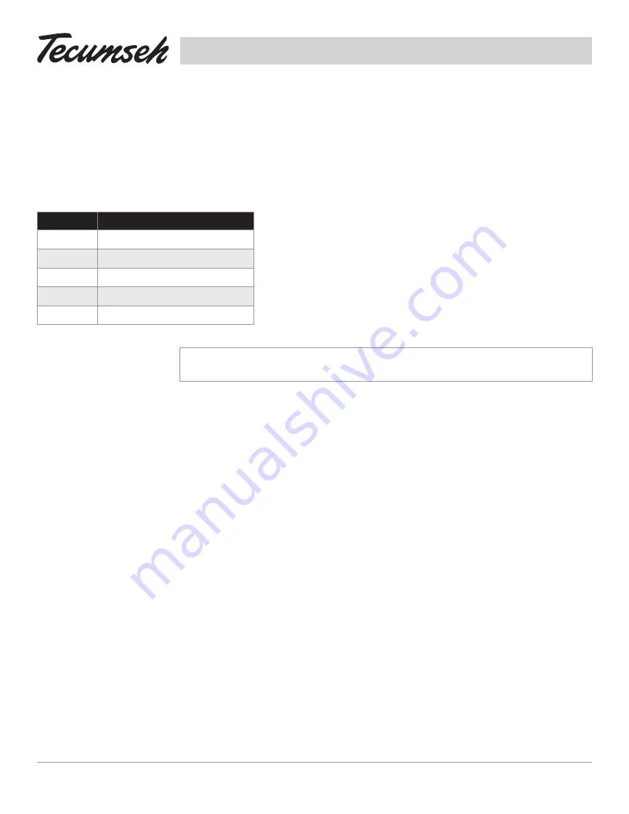
Generally the wiring diagrams will show all electrical components, even those that are
offered as options or should be supplied and installed by others.
Should any component be added to the unit as a field supplied option then the wiring
should follow the given diagram (chart on left / diagrams in Appendix).
WD Number Description
91292
115V & 208-230V 60 Hz/ 1 Phse, 1 Fan
91293
208-230V 60 Hz/ 1 Phse, 2 Fan
91293-1
200-230V 60 Hz/ 3 Phse, 2 Fan
91294
200-230V 60 Hz/ 3 Phse, 1 Fan
91294-1
208-230V 60 Hz/ 1 Phse, 1 Fan
CAUTION:
Any non-compliance with voltage ranges and phase balances or any altering of electrical
components without Tecumseh written approval will void the warranty.
PIPING
(See Suction and Liquid Line Sizes in Appendix)
Employ only Refrigeration grade copper tubing. Always keep the tubes free of moisture and dirt and remove any
burrs present on the tubes. The thermostatic expansion valve must be the externally equalized type. It can be
mounted inside the unit cooler end compartment. Mount the expansion valve bulb on a horizontal run of suction
line as close as possible to the suction header. Use the clamps provided with the valve to fasten the bulb securely
so there is a tight line-to-line contact between the bulb and the suction line. Suction and liquid connections are
made on the outside of the unit.
Standard piping practices and local/national codes should be employed to size and install refrigerant gas
and liquid lines.
A) The selection of the suction gas line sizes should be guided by the following criteria:
• Assurance of adequate velocity, thus ensuring oil return capability (the tube size must be limited to maintain
velocities no less than 750 fpm for horizontal and down flow and no less then 1500 fpm for up flow)
• Assurance of acceptable pressure drop (The tube size should be limited to maintain pressure drop
no greater than the equivalent of a 2°F temperature drop.)
• Assurance of satisfactory sound level (the tube size should be limited to maintain velocities
no greater than 3000 fpm.)
Horizontal suction lines should be sloped downward in the direction of the compressor at least ½” per 10’ of line.
The appendix tables recommend suction line sizes for installations where the line is horizontal or down flow. In the
event the suction line is up flow, use “one standard size” smaller. A suction trap should be installed at the base of
suction risers. Prefabricated wrought copper traps are available, or a trap can be made by using two street ells and
Содержание Argus
Страница 1: ...Remote Condensing Unit Installation Instructions ...
Страница 35: ...NOTES ...


