


12
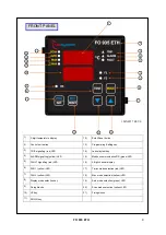
FO 935 ETH
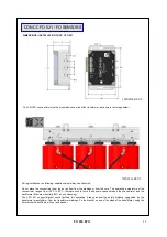
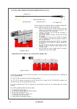
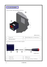
The FO sensors must be inserted inside the secondary winding of the
transformer always respecting the following indications:
•
each U-V-W sensor must be inserted inside the secondary
winding of the transformer, the sensor connected to CH2
must be positioned in the central column;
•
insertion of the probe must not find any restrictions or
occlusions of any kind;
•
avoid twisting, straining or jerking. The fibre sensors could
be damaged;
•
the connection of the sensors to the CFO 521 concentrator
must be laid linearly, with a maximum radius of curvature of
8mm, not less than 90°;
•
the connection of the sensors to the CFO 521 concentrator
must be made with the original ST connector supplied with
the sensor;
•
any excess of the probes must be wound with a minimum
diameter of 50mm, using the winder located on the
mounting bracket;
•
once the probes have been installed, apply the protection
bracket using the M4 screws supplied.
FO (OPTICAL FIBRE) TEMPERATURE SENSOR DIMENSIONS/INSTALLATION
READING POINT
ST CONNECTOR
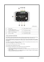
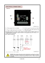
CONNECTION OF THE CONC.CFO 521 / TO THE FO 935 CONTROL UNIT
For correct connection of the CFO 521 concentrator to the thermometric control unit, the following rules must be strictly
observed:
Note: All the signal transportation cables must strictly:
•
be separated from those of power
•
be created with shielded cable with twisted conductors
•
have a section of at least 0.25 mm²
•
the shield must be earthed on one side only
•
be firmly fixed in the terminal blocks
•
have tin-plated or silver-plated conductors
Connect the FO IN input of the CFO521 concentrator to the FO IN input of the FO 935 control unit, respecting the
numbering
B1-B2-B3-B4.
The FO OUT output is not used (provision for future development).
The CFO 521 concentrator is powered by the FO 935 control unit, through the FO IN B1-B2-B3-B4 connection bus,
therefore it does not require an external power supply.
1MN0227 REV.0
1MN0228 REV.0
1MN0228 REV.0