background image

Manual de uso 

291

ES

15

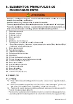
   Pedal control destalonador (pedal monoestable para accionar la paleta destalo

-

nadora

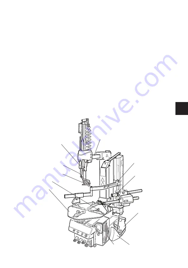
8.1.b. BRAZO HORIZONTAL

22

   Pulsador subida/bajada brazo vertical A: subida; B: bajad;a C: bloqueado

23

   Palanca de mando torreta

8.1.c. PRENSA-TALÓN

26

   Válvula de mando subida/bajada TPH

27

   Válvula de mando de avance del disco TPH

8.1.d. MANÓMETRO CON PULSADOR DE DESINFLADO 

20

   Pistola con manómetro

21

   Pulsador para desinflar neumático

1

2

4

6

7

9

10

11

5

31

32

28

Содержание TECO 36 TOP

Страница 1: ...Automotive Equipment Instruction Manual SMONTAGOMME TYRE CHANGERS TECO 36 TOP Cod 4 139257 January 2020 IT EN FR DE ES ...

Страница 2: ... essere considerato parte integrante dell attrezza tura e accluso alla stessa Tuttavia nulla di quanto è contenuto nel presente manuale e nessun di spositivo installato sull attrezzatura sostituisce un adeguata formazione un funzionamento corretto un attenta valutazione e delle procedure di lavoro in sicurezza Assicurarsi che l attrezzatura sia sempre in condizioni ottimali di esercizio Nel caso i...

Страница 3: ...ega Cerchi con canale rovescio Bloccaggio interno esterno con griffe in acciaio Stallonatura Ruote standard Ruote ribassate Smontaggio Corretto posizionamento torretta per evitare danneggiamenti Lubrificazione del tallone in fase di rimozione di pneumatici ribassati Cerchi con canale rovescio Montaggio Ruote standard Montaggio di pneumatici ribassati rigidi Ruote con canale rovesciato Lubrificazio...

Страница 4: ..._______________________ ___________________________________________________ ___________________________________________________ ___________________________________________________ ___________________________________________________ ___________________________________________________ ___________________________________________________ ___________________________________________________ ...

Страница 5: ...EDURE DI BASE UTILIZZO 29 9 1 CONTROLLI PRELIMINARI 30 9 2 STABILIRE DA QUALE LATO DELLA RUOTA SMONTARE LO PNEU MATICO 30 9 3 STALLONATURA 31 9 4 BLOCCAGGIO RUOTA 33 9 5 SMONTAGGIO DELLA RUOTA 34 9 6 MONTAGGIO DELLA RUOTA 41 9 7 Il GONFIAGGIO DEI PNEUMATICI 44 10 RISOLUZIONE DEI PROBLEMI 50 11 MANUTENZIONE 52 12 INFORMAZIONI SULLA DEMOLIZIONE 54 13 INFORMAZIONI AMBIENTALI 54 14 INDICAZIONI E AVVER...

Страница 6: ...orsivo è utilizzato per fare riferimento a parti specifiche del presente manuale che offrono infor mazioni aggiuntive o chiarimenti Tali riferimenti devono essere letti per ottenere delle informazioni aggiuntive alle istruzioni presentate Il proprietario dell attrezzatura è il solo responsabile dell osservanza alle procedure di sicurezza e dell organizzazione della formazione tecnica L attrezzatur...

Страница 7: ... potrebbero verificarsi incidenti All interno del presente manuale vengono fatti riferimenti continui alla possibilità che si verifichino incidenti Qualsiasi incidente potrebbe provocare infortuni gravi o mortali per l operatore o i passanti o provocare danni materiali 2 Pneumatici eccessivamente gonfi possono esplodere provocando la dispersione in aria di detriti che possono causare incidenti 3 P...

Страница 8: ...esso di smontaggio e di montaggio Tenere mani e dita lontane dalla testina durante il funzionamento Tenere mani e altre parti del corpo lontane dalle parti in movimento Non utilizzare utensili diversi da quelli forniti con lo smontagomme Utilizzare del lubrificante per pneumatici adeguato al fine di evitare il grippaggio dello pneumatico Prestare attenzione durane la movimentazione del cerchio o d...

Страница 9: ...re sulla capacità di far fun zionare la macchina in sicurezza 17 Utilizzare sempre dispositivi di protezione individuale DPI approvati e autorizzati OSHA CE o con certificazioni equivalenti durante il funzionamento della macchina Consultare il supervisore per ulteriori istruzioni 18 Non indossare gioielli orologi abiti ampi cravatte e legare i capelli lunghi prima di utilizzare la macchina 19 Indo...

Страница 10: ...RED Mod V A kW Hz Ph bar psi ADESIVO MATRICOLA MODELLO 02 000101200 ADESIVO PEDALE RIBALTAMENTO PALO ADESIVO PEDALE CHIUSURA APERTURA AUTOCENTRANTE ADESIVO PEDALE STALLONATORE ADESIVO PEDALE ROTAZIONE AUTOCENTRANTE 03 000102700 ADESIVO DIVIETO COLLEGAMENTO ALIMENTAZIONE PNEUMATICA ADESIVO RACCORDO DOYFE 04 000105200 ADESIVO PEDALE DI GONFIAGGIO solo versione T I ...

Страница 11: ...SIVO PERICOLO SCHIACCIAMENTO MANI AUTOCENTRANTE 07 000103300 ADESIVO PERICOLO SCHIACCIAMENTO MANI STALLONATORE 08 000103400 ADESIVO PERICOLO SCHIACCIAMENTO GAMBE STALLONATORE 09 000102900 ADESIVO PERICOLO ROTAZIONE PALO 10 000103100 ADESIVO PERICOLO MANI TORRETTA ADESIVO PERICOLO MANI AUTOCENTRANTE 11 4 603201 ADESIVO PERICOLO ESPLOSIONE ...

Страница 12: ...O FRECCIA CENTRALINA 15 4 601628 ADESIVO COMANDO UTENSILE 16 ADESIVO PRESSORE 17 425211A ADESIVO PERICOLO TENSIONE 18 4 602923 ADESIVO 2 SPEED 19 LOGO LOGO LOGO 1 2 c LEGENDA ETICHETTE DI PERICOLO parte n 000102800 PERICOLO USCITA ARIA IN PRESSIONE parte n 000103200 PERICOLO SCHIACCIAMENTO MANI AUTOCENTRANTE ...

Страница 13: ...AMBE STALLONATORE parte n 000102900 PERICOLO ROTAZIONE PALO parte n 000103100 PERICOLO SCHIACCIAMENTO MANI parte n 425211A PERICOLO SCOSSA ELETTRICA parte n 4 603202 PERICOLO DI ESPLOSIONE parte n 000103900 TERMINALE DI COLLEGAMENTO A TERRA parte n 446237 TERMINALE DI COLLEGAMENTO A TERRA parte n 4 603201 PERICOLO DI ESPLOSIONE ...

Страница 14: ...14 Manuale Operatore 01 05 02 18 04 08 06 07 10 11 12 14 15 16 16 19 17 ...

Страница 15: ...n sensi bilità 30mA montare dei fusibili di protezione della linea di alimentazione dimensionati secondo le indicazioni riportate nell apposita targhetta dati macchina Fig 1 collegare la macchina ad una presa industria le non è consentito il collegamento a prese domestiche Assicurarsi che la pressione disponibile e le prestazioni dell impianto ad aria compressa sianocompatibiliconquellenecessariea...

Страница 16: ...alo completamente ribaltato A B 1 2 e DATI TECNICI Capacità di bloccaggio autocentrante 10 25 dall interno 13 25 dall esterno 10 22 Larghezza cerchio 370 mm 14 5 Diametro max ruota 1060 mm 41 5 Forza di stallonatura 2900 Kg Pressione di esercizio 8 10 Bar Caratteristiche elettriche motore versione 200 230V 1ph 50Hz _ 1 speed 6A 0 75 kW versione 200 230V 3ph 50Hz _ 1 speed 2 8A 0 55 kW versione 400...

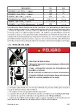
Страница 17: ...ntiti possono variare da paese a paese In ogni caso queste informazioni consentiranno all utente della macchina di effettuare una migliore valutazione del pericolo e del rischio 1 2 f PRESSIONE DELL ARIA PERICOLO PERICOLO DI ESPLOSIONE Non oltrepassare la pressione raccomandata dal fabbricante dello pneumatico Fare corrispondere sempre le dimensioni di pneu matico e cerchio Fareattenzioneadeventua...

Страница 18: ...te in merito ai pericoli derivanti dalla manutenzione delle stesse e le procedure di sicurezza da osservare Per Servizio o Manutenzione si intende il montaggio e lo smontaggio di ruote e tutte le attività a queste correlate quali il gonfiaggio lo sgonfiaggio l installazione la rimozione e la movimentazione Il datore di lavoro è tenuto ad assicurarsi che gli operatori non intervengano sulle ruote a...

Страница 19: ...la macchina Ad intervalli periodici In seguito a riparazioni La macchina deve essere avviata solo dopo aver correttamente completato questi controlli preliminari Non usare la macchina se messa fuori servizio per messa a punto manuten zione lubrificazione ecc 1 7 DURANTE L UTILIZZO Qualora vengano percepiti rumori strani o vibrazioni inconsuete se un componente o si stema non funziona correttamente...

Страница 20: ...llo standard 440kg versione t i 460kg Condizioni dell ambiente di trasporto e stoccaggio macchina Temperatura 25 55 C ATTENZIONE Per evitare danneggiamenti non sovrapporre altri colli sull imballo Movimentazione Per lo spostamento dell imballo infilare le forche di unmulettonegliappositiscassipostisulbasamento dell imballo stesso pallet Fig 3 Per lo spostamento della macchina fare riferimento alca...

Страница 21: ...dal pallet assicurarsi che dallo stesso siano stati rimossi gli elementi mostrati qui di seguito Liberare la macchina dalla parte superiore dell imballo accertarsi che non abbia subito danni durante il tra sportoeindividuareipuntidifissaggio al pallet La macchina è composta da 1 cassone 2 testata 3 helper 4 dotazione 5serbatoioaria soloversioneT I 4 MONTAGGIO Versione T I Inserireilbocchettonedels...

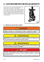
Страница 22: ... la macchina dalla rete elettrica e pneumatica di alimentazione 5 1 SPAZIO DI INSTALLAZIONE ATTENZIONE Installarelamacchinaconformementeatuttelenormesullasicurezzaapplicabili incluse ma non limitate ad esse quelle emesse da OSHA AVVERTENZA IMPORTANTE peruncorrettoesicuroutilizzodell attrezzatura raccomandiamo un valore di illuminazione dell ambiente di almeno 300 lux AVVERTENZA IMPORTANTE Non inst...

Страница 23: ...he la macchina rimane scollegata dalla linea pneumatica per lunghi periodi prima di ripristinare l alimentazione pneumatica verificare la configura zione dei pedali di comando come di seguito illustrato PERICOLO Prima di procedere all allacciamento elettrico e pneumatico e ogni volta che viene ripristinata l alimentazione elettrica e pneumatica assicurarsi che la macchina sia nella configurazione ...

Страница 24: ...tenza assorbita in kW Hz Frequenza in Hz Ph Numero delle fasi bar psi Pressione di esercizio in bar e o psi SerialN ilnumerodimatricoladellamac china ISO 9001 Certificazione del Sistema Qualità della società CE marcatura CE 6 1 POSIZIONE DELL OPERATORE In fig 9a sono rappresentate le posizioni occupate dall operatore e le relative zone perico lose P durante le varie fasi di lavoro A Stallonatura B...

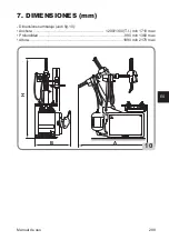
Страница 25: ...Manuale Operatore 25 IT 7 DIMENSIONI D INGOMBRO mm Dimensioni di ingombro vedi fig 10 Lunghezza 1200 1300 T I min 1710 max Larghezza 990 min 1360 max Altezza 1890 min 2170 max B A H 10 ...

Страница 26: ... regolare filtrare deumidificare e lubrificare l aria di alimentazione 9 Braccio stallonatore 10 Paletta stallonatore 11 Appoggio stallonatore 18 Pedale di gonfiaggio 19 Manometro 24 Cilindro per discesa torretta mobile 25 Cilindro comando utensile smontaggio 28 Gancio bloccaggio braccio 29 Braccio premi tallone 30 Utensile premi tallone 31 Rullo premitallone 32 Braccio alzatallone 33 Leva alzatal...

Страница 27: ...RACCIO ORIZZONTALE 22 Pulsante salita discesa braccio verticale A salita B discesa C bloccato 23 Leva comando torretta 8 1 c PREMITALLONE 26 Valvola comando salita discesa TPH 27 Valvola comando avanzamento disco TPH 8 1 d MANOMETRO CON PULSANTE DI SGONFIAGGIO 20 Manometro 21 Pulsante di sgonfiaggio 1 2 4 6 7 9 10 11 5 31 32 28 ...

Страница 28: ... 25 24 29 30 34 ATTENZIONE PERICOLO DI ESPLOSIONE Per le caratteristiche tecniche avvertimenti manutenzione e qualsiasi altra informazione relativa al serbatoio dell aria op zionale il manuale d uso e manutenzione fornito insieme alla documentazione dell accessorio ...

Страница 29: ...e un potenziale pericolo di urto con parti del corpo B A C P P ATTENZIONE EVITARE DANNI FISICI Prima di effettuare interventi di ma nutenzione sulla macchina 1 Mettere la macchina in configura zione stabile con l asse orizzontale completamente arretrato ed il palo in posizione di lavoro 2 Staccare la spina di alimentazione Fig 12a 3 Isolare la linea di aria compressa scollegando la valvola di chiu...

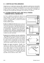
Страница 30: ...UOTE SPECIALI Ruote con cerchi in lega alcune ruote con cerchi in lega presentano un canale del cerchio A minimo o non presentano alcun canale Fig 13A Tali cerchi non sono approvati dagli standard del DOT Depart ment of Transportation Dipartimento dei trasporti La sigla DOT certifica la conformità degli pneumatici agli standard di sicurezza adottati dagli Stati uniti e il Canada tali ruote non pos...

Страница 31: ...etamente abbassato In questa configurazione le griffe sono completamente chiuse Fig 14a Sgonfiare completamente il pneumatico rimuovendo l interno valvola Fig 14b Regolare l appoggio cerchio in base al diametro della ruota Regolare la posizione della paletta in base alla lar ghezza della ruota tramite il perno A fig 15 in modo da ottenere una miglior inclinazione della paletta sul fianco del pneum...

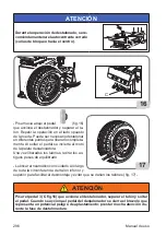
Страница 32: ...o da liberare il tallone completamente Ilrilasciodelpedaleinverteilmotodellapaletta stallonatrice Una volta staccati i talloni rimuovere i vecchi pesi d equilibratura Lubrificareconcurailpneumaticolungotutta la circonferenza del tallone inferiore e di quello superiore per agevolare lo smontaggio ed evitare danni ai talloni fig 17 ATTENZIONE L azionamento del pedale stallonatore C fig 16 causa la c...

Страница 33: ...posizione di fuori lavoro Premere il pedale per portare la colonna in posizione di fuori lavoro L apertura e la chiusura delle griffe dell auto centrante avviene premendo sequenzialmente il pedale di comando Fig 18 Con le griffe completamente chiuse premere leggermente il pedale di comando e portarlo in posizione centrale Fig 18 In questa configu razione è possibile comandare l apertura delle grif...

Страница 34: ...centrante ad una misura leggermente superiore a quella della ruota appoggiare la ruota sul piatto autocentrante posizionare il braccio premi cerchio in posizione di lavoro Fig 20a azionare la valvola in modo da premere la ruota sul piatto quindi bloccare la ruota con apposito pedale N B Questa operazione facilita l inserimento del cuneo della griffa tra gomma e cerchio Fig 20a 20a 20 9 5 SMONTAGGI...

Страница 35: ...B Assicurarsi che il posizionamento sia corretto aiutandosi con la maniglia 2 Fig 21a Premere il blocco 1 Fig 21a per fissare la posi zione dell utensile Lo spazio fra cerchio e torretta rimane inalterato finché il pulsante è in posizione di bloccaggio L operatore può ribaltare liberamente il palo ad esempionelcasodismontaggiodelleruotediuguale misura senza dover riposizionare la torretta Pre star...

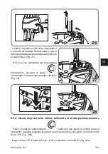
Страница 36: ...piccola rota zione dell autocentrante 24 1 2 1 25 9 5 c Smontaggio del tallone superiore Verificare che l utensile abbia agganciato il tallone del pneumatico Azionareilcomando perprepararsiallasuccessivaoperazionedismontaggio operazione da eseguire da fermo e non in rotazione Fig 26 Verificare che il pneumatico non si sia rintallonato sul lato vicino all operatore Even tualmente aiutarsi con morse...

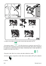
Страница 37: ...io del tallone Fig 28 28 9 5 d Smontaggio del tallone inferiore con utilizzo della torretta portautensile Premere il pedale autocentrante fino a che una griffa non sia rivolta verso l ope ratore e la freccia gialla posta sull autocentrante sia in direzione del disco TPH Fig 29a Abbassare il braccio TPH fino a fine corsa utilizzando il comando 26 Fig 29b Sollevare il pneumatico in corrispondenza de...

Страница 38: ...ll autocentrante sino a portare il tastatore a contatto con il bordo inferiore del cerchio Automaticamente il braccio alzatallone si distanzierà dal cerchio si 2 3mm Esercitare una spinta con il disco alzatallone sul tallone inferiore utilizzando il comando B Fig 29c Utilizzando il comando azionare l uncino e agganciare il tallone inferiore del pneumatico C Fig 29c ...

Страница 39: ...utensile Premere il pedale autocentrante fino a che una griffa non sia rivolta verso l operatore e la freccia gialla posta sull autocentrante sia in direzione del disco TPH Abbassare il braccio TPH fino a fine corsa utilizzando il comando Sollevare il pneumatico in corrispondenza dell utensile alzatallone del TPH Azionare il comando posto sulla consolle di comando del TPH il braccio alzatallone sc...

Страница 40: ...e fino al completo smontaggio del pneumatico D Fig 30 9 5 f Smontaggio completato A smontaggio completato azionare il commutatore posto sulla consolle di comando del TPH per fare arretrare l utensile alzatallone sino alla sua posizione di riposo ribaltare il palo con il pedale di ribaltamento palo e quindi rimuovere lo pneu matico Fig 31 31 ...

Страница 41: ...rte Controllare anche che i cerchioni non siano deformati che i loro fori di fissaggio non siano diventati ovale che essi non siano incrostati o arrugginiti e che essi non abbiano bavature affilate sui fori della valvola Verificare che lo pneumatico sia in buone condizioni e non vi siano segni di danni 9 6 a Preparazione del pneumatico Ingrassare entrambi i talloni del pneumatico Fig 32 Posizionar...

Страница 42: ...attenzione che il pneumatico non scivoli sotto l utensile 9 6 e Posizionamento del rullo premitallone Avvicinare il rullo premitallone al bordo del cerchio 2 3mm e bloccarne la posizione avvitando la manopola Fig 33a Abbassare il rullo premitallone comando fino a livello del canale cerchio Fig 33b 2 1 33a 33b 9 6 f Montaggio tallone superiore Avviare la rotazione pedale per montare il tallone Prem...

Страница 43: ...te al pneumatico man tenendolo nel canale e consentendo l inserimento del secondo tallone senza sforzo e senza rischi per l operatore o di danneggiamento del pneumatico 34a 34b ATTENZIONE Quando il premi tallone si trova ad ore 6 circa diminuire la pressione del dispo sitivo comando 26 in modo da evitare possibili danni al tallone Completato il montaggio alzare il premi tallone e il rullo comando ...

Страница 44: ...napressioneadore3 Riprendere la rotazione fino al completo montaggio del pneumatico Rimovuere il morsetto il premitallone l utensile e il rullo premitallone Portare il gruppo premitallone e rullo in posizione di riposo 9 7 Il GONFIAGGIO DEI PNEUMATICI 9 7 a Indicazioni di sicurezza PERICOLO PERICOLO DI ESPLOSIONE Non oltrepassare la pressione raccomandata dal fabbricante dello pneumatico Farecorri...

Страница 45: ...gonfi possono esplodere provocando la dispersione in aria di detriti che possono causare incidenti 2 Pneumatici e cerchi che non hanno lo stesso diametro sono detti non corrispondenti Non tentare di montare o gonfiare degli pneumatici con dei cerchi non corrispondenti Ad esempio non montare mai uno pneumatico da 16 su un cerchio da 16 5 o vicever sa È molto pericoloso Pneumatici e cerchi non corri...

Страница 46: ...hio o lo pneumatico sono difettosi o danneggiati Non oltrepassare mai la pressione raccomandata dal fabbricante dello pneu matico 9 7 b GONFIAGGIO DEGLI PNEUMATICI Assicurarsi che la ruota NON sia bloccata sull autocentrante per mezzo delle griffe di centraggio Fig 35 Inserire il cono di centraggio sul bracciopremicerchio portareilbrac cio in posizione di lavoro azionare il comando finoaportareil ...

Страница 47: ...zione lubrificare e fare ruotare lo pneumatico sul cerchio Ripetere l operazione di montaggio descritta in precedenza con ulteriore verifica 37 38 39 ATTENZIONE Pericolo di esplosione Durante la fase di intallonatura non oltrepassare la pres sione massima indicata del costruttore riportata sul fianco dello pneumatico Una volta effettuata l intallonatura rimontare la parte interna della valvola e q...

Страница 48: ...ante dalla parte interna fig 40 Inserire il cono di centraggio sul braccio premi cerchio portare il braccio in posizione di lavoro azionare il comando 16 fino a portare il cono a contatto con il cerchio Fig 36 Togliere il nucleo della valvola qualora non fosse già stato rimosso Fig 37 Collegare il raccordo Doyfe del tubo di gonfiaggio allo stelo della valvola Fig 38 Premere a fondo per un breve in...

Страница 49: ...O DI ESPLOSIONE Non montare uno pneumatico e un cerchio che non presentano lo stesso diametro ad esempio pneumatico da 16 pollici e 1 2 con un cerchio da 16 pollici Nel caso lo pneumatico sia eccessivamente gonfio è possibile togliere l aria premendo il pulsante manuale di sgonfiaggio in ottone ubicato sotto il manometro della pressione aria Fig 43 Scollegare il tubo di gonfiaggio dallo stelo dell...

Страница 50: ... connessioni del cavo nella spina Il motore non gira Controllare i microinterruttori della pedaliera solo per motoinverter Controllare il comando rotazione motore della pedaliera Sostituire la scheda inverter solo per motoinverter Sostituire motore La cinghia è rotta Sostituire cinghia Riduttore bloccato Sostituire il riduttore Autocentrante non gira in un senso o nell altro Comando difettoso Sost...

Страница 51: ...chio Piastrina bloccaggio non registrata Registrare piastrina Palo non apre Cilindro apertura palo difettoso Sostituire cilindro apertura palo Non arriva aria al cilindro Tubi piegati Sostituire valvola Cilindretti bloccaggio braccio perdono aria Pistone o guarnizioni difettosi Sostituire pistoni e guarnizioni Il palo ribalta con violenza o troppo lentamente Regolatori di scarico starati Registrar...

Страница 52: ...ssione ATTENZIONE Primadiprocedereconqualsiasioperazionedimanutenzioneordinariaorabboc co lubrificante scollegare la macchina dalla linea di alimentazione pneumatica ATTENZIONE Il costruttore declina ogni responsabilità in caso di reclami derivati dall uso di ricambi o accessori non originali Pulire regolarmente la macchina da sporcizia Mantenere pulite e lubrificate tutte le guide asse verticale ...

Страница 53: ...tore FR è dotato di un sistema automatico per lo scarico dall acqua della condensa quindiincondizionidiutilizzonormalinonnecessitadiparticolaremanutenzione è possibile comunque in qualsiasi momento provvedere allo scarico manuale fig 47d Normalmente non è necessario smontare le tazze ma per operazioni di manutenzione dopo lunghi periodi di utilizzo si può verificare tale necessità se non fosse suf...

Страница 54: ...uente procedura di smaltimento deve essere applicata esclusivamente alle macchine in cui la targhetta dati macchina riporta il simbolo del bidone barrato Questo prodotto può contenere sostanze che possono essere dannose per l ambiente e per la salute umana se non viene smaltito in modo opportuno Vi forniamo pertanto le seguenti informazioni per evitare il rilascio di queste sostanze e per migliora...

Страница 55: ... l uso delle discariche per lo smaltimento dei prodotti e migliorare la qualità della vita evitando che sostanze potenzialmente pericolose vengano rilasciate nell ambiente 14 INDICAZIONI E AVVERTENZE SULL OLIO Smaltimento olio usato Non gettare l olio usato in fognature cunicoli o corsi d acqua raccoglierlo e consegnarlo ad aziende autorizzate per la raccolta Spargimento o perdite d olio Contenere...

Страница 56: ...resto al presidio medico Pelle lavare con acqua e sapone 15 MEZZI ANTINCENDIO DA UTILIZZARE Per la scelta dell estintore più adatto consultare la tabella seguente 15 1 Materiali secchi Idrico SI Schiuma SI Polvere SI CO2 SI 15 2 Liquidi infiammabili Idrico NO Schiuma SI Polvere SI CO2 SI 15 3 Apparecchiature elettriche Idrico NO Schiuma NO Polvere SI CO2 SI SI Utilizzabile in mancanza di mezzi più...

Страница 57: ... buona resistenza all abrasione e una buona aderenza in condizioni di asciutto e bagnato così come delle condizioni di funzionamento silenziose 2 Bordo o rinforzo È un inserto di tessuto me tallico o tessile disposto in corrispondenza della parte esterna del tallone serve a proteggere le tele della carcassa dallo strisciamento contro il cerchio 3 Carcassa Costituisce la struttura resistente ed è c...

Страница 58: ... che indica la circonferenza della parte supe riore del tallone ed è utilizzato come riferimento per controllare il corretto centraggio dello pneumatico sul cerchio dopo il montaggio 7 Cordolo di protezione È un rilievo circonfe renziale posto nella zona del fianco più esposta a strisciamenti accidentali 8 Fianco È la zona compresa tra la balconata e il cordolo di centratura È costituito da uno st...

Страница 59: ...eumatici tubeless sono formati da uno pneuma tico con fianco interno rivestito da un sottile strato di gomma speciale impermeabile chiamato liner Questo contribuisce ad assicurare la tenuta dell aria inpressionecontenutanellacarcassa Questotipodi pneumatici deve essere montato su cerchi specifici direttamente sui quali è fissata la valvola II Cerchio Ruota Il cerchio è l elemento rigido in metallo...

Страница 60: ...mo interno b e il fondello c rivestimento esterno Gonfiatubeless Sistema di gonfiaggio che facilita il gonfiaggio dei pneumatici tubeless Intallonatura Operazione che si ottiene nella fase di gonfiaggio e garantisce un perfetto centraggio tra tallone e bordo cerchio Pinza premi tallone E un utensile adibito ad essere utilizzato durante il montaggio del tallone superiore È sistemata in modo che agg...

Страница 61: ...3 4 x 1 2 L 0 R 1 2 3 L1 ELEMENTI Elements CONTATTI Contacts W2 U1 U2 V2 V1 W1 W2 U1 U2 V2 V1 W1 200 220 240V 380 415 440V MORSETTIERA Junction Box F F F Power Phase 400V 3 50 Hz 0 55 kW 500V 4A 400V 3 50 Hz 0 75 kW 500V 6A 230V 3 50 Hz 0 55 kW 250V 10A 230V 3 50 Hz 0 75 kW 250V 10A 200V 3 50 Hz 0 75 kW Japan 250V 10A F Fuse TYRE CHANGER 1 SPEED VERSION 3 PHASE 17 SCHEMA ELETTRICO GENERALE ...

Страница 62: ... 11 12 x 9 10 x 7 8 x 5 6 x 3 4 x 1 2 L 0 R 1 2 3 ELEMENTI Elements CONTATTI Contacts F F Power Phase Neutral 230V 1 50 Hz 250V 16A 250V 16A 240V 1 50 Hz 250V 16A 250V 16A 220V 1 60 Hz 250V 16A 250V 16A 115V 1 60 Hz 250V 20A 250V 20A F Fuse W2 U1 U2 V2 V1 W1 C 3 2 8 12 MORSETTIERA Junction Box AUTOMATIC TYRE CHANGER version TYRE CHANGER 1 SPEED VERSION 1 PHASE ...

Страница 63: ...ts 1 3 5 7 9 11 2 4 6 8 10 12 13 15 17 19 21 23 14 16 18 20 22 24 L2 23 24 x x x 21 22 x 19 20 x 17 18 x x 15 16 x x 13 14 x 11 12 x 9 10 x 7 8 x x 5 6 x x 3 4 x 1 2 L2 L1 0 R 1 2 3 4 5 6 V2 U2 W2 W1 V1 U1 PE 22 13 15 24 9 11 F F F Power Phase 400V 3 50 Hz 500V 6A 230V 3 50 Hz 250V 16A 400V 3 60 Hz 500V 6A 230V 3 60 Hz 250V 12A F Fuse TYRE CHANGER 2 SPEED VERSION 3 PHASE ...

Страница 64: ...HANGER MOTOINVERTER VERSION AP1 N PE L1 F F XS1 L1 N SQ3 XB1 SQ1 SQ2 M1 R T S 1 2 3 4 U V W BROWN BLACK BLUE GRUPPO MOTORE MOTOR UNIT GRUPPO COMANDI CONTROL SWITCH Power Phase Neutral 200 230V 1 50 60 Hz 250V 12A 250V 12A F Fuse ...

Страница 65: ...Manuale Operatore 65 IT 18 SCHEMA IMPIANTO PNEUMATICO P max 12 bar 33 32 31 30 29 28 1 2 4 3 5 6 7 8 9 10 11 12 12 13 13 15 14 34 35 36 16 17 19 18 20 21 22 23 24 25 27 26 H G F E D N L M I A B C ...

Страница 66: ...Note ...

Страница 67: ...Note ...

Страница 68: ...ruction Manual should be considered an integral part of your equipment and should remain with the equipment However nothing in this manual and none of the devices installed on the equipment can replace proper training correct operation careful evaluation of procedures and safe working practices Always be sure that your equipment is in excellent working order In case any malfunction or possible dan...

Страница 69: ...Internal external locking with steel jaws Bead breaking Standard wheels Low profile wheels Demounting Standard wheels with plastic guards for tool head and lever Proper tool head positioning to avoid damage Bead lubrication when removing the low profile tyres Reverse rims Mounting Standard wheels Mounting of stiff low profile tyres Wheels with reversed channel rim Bead lubrication for proper mount...

Страница 70: ...___________________ ___________________________________________________ ___________________________________________________ ___________________________________________________ ___________________________________________________ ___________________________________________________ ___________________________________________________ ___________________________________________________ ...

Страница 71: ...POSITION 90 7 OVERALL DIMENSIONS mm 91 8 MAIN WORKING ELEMENTS OF THE MACHINE 92 8 1 COMMANDS 92 9 BASIC PROCEDURES USE 95 9 1 PRELIMINARY CHECKS 96 9 2 DECIDING FROM WHICH SIDE OF THE WHEEL THE TYRE MUST BE REMOVED 96 9 3 BEAD BREAKING 97 9 4 CLAMPING THE WHEEL 98 9 5 WHEEL DEMOUNTING 100 9 6 WHEEL mounting 107 9 7 TYRE INFLATION 110 10 TROUBLESHOOTING 116 11 MAINTENANCE 118 12 SCRAPPING 120 13 E...

Страница 72: ...edures and maintenance Italics are used to refer to specific parts of this manual that offer additional information or clarifications These references must be read in order to obtain information additional to the instructions provided The owner of the equipment is solely responsible for enforcing safety procedures and arranging technical training The equipment must only be used by qualified specif...

Страница 73: ... instructions it contains are not observed This manual makes continuous reference to the possibility that accidents can occur Any accident could lead to serious or fatal injuries to the operator or people nearby or cause material damage 2 Overinflated tyres can explode producing hazardous flying debris that may result in an accident 3 Tyres and rims that do not have the same diameter do not corres...

Страница 74: ... parts away from moving parts Do not use tools other than those supplied with tyre changer Use lubricant that is specific for tyres in order to prevent tyre seizure Pay attention while handling the rim or the tyre and while using the lever 8 Danger of electric shock Do not clean electric parts with water or high pressure air jets Donotoperatethemachineinthepresenceofadamagedelectricalcable If an e...

Страница 75: ...ipment PPE orequipmentwithequivalentcertificationswhileoperating the machine Consult your supervisor for additional instructions 18 Do not wear jewellery watches loose clothing ties and tie up long hair before using the machine 19 Wear protective non slip footwear while using the tyre changer 20 While positioning lifting or removing wheels from the tyre changer wear an appropriate back support and...

Страница 76: ... DI COSTRUZIONE MANUFACTURED Mod V A kW Hz Ph bar psi LABEL MODEL SERIAL NUMBER 02 000101200 LABEL tilting column LABEL TURNTABLE OPE NING CLOSING LABEL BEAD BREAKER ACTIVATION LABEL ROTATION TURNTABLE 03 000102700 LABEL do not connect pressurized devices LABEL DOYFE UNION 04 000105200 LABEL INFLATION PEDAL only T I version ...

Страница 77: ...06 000103200 LABEL HAND CRUSHING HAZARD TURNTABLE 07 000103300 LABEL HAND CRUSHING HAZARD BEAD BREAKER 08 000103400 LABEL LEG CRUSHING HAZARD BEAD BREAKER 09 000102900 LABEL RISK OF INJURY REAR POLE 10 000103100 LABEL DANGER TOOL HEAD LABEL DANGER TURN TABLE 11 4 603201 LABEL DANGER OF INFLA TION ...

Страница 78: ...ATION DIREC TION 15 4 601628 LABEL Moving tool head mounting de mounting control 16 LABEL TPH CONTROL 17 425211A LABEL DANGER OF ELEC TRIC SHOCK 18 4 602923 LABEL 2 SPEED 19 LOGO LOGO LOGO 1 2 c HAZARD LABELS KEY part n 000102800 LABEL DANGER PRESSURISED CONTAINER part n 000103200 LABEL HAND CRUSHING HA ZARD TURNTABLE ...

Страница 79: ...KER part n 000102900 LABEL RISK OF INJURY REAR POLE part n 000103100 LABEL DANGER TOOL HEAD LABEL DANGER TURNTABLE part n 425211A LABEL DANGER OF ELECTRIC SHOCK part n 4 603202 LABEL RISK OF EXPLOSION part n 000103900 LABEL Earth ground termi nal part n 446237 LABEL Earth ground termi nal part n 4 603201 LABEL DANGER OF INFLATION ...

Страница 80: ...80 User s manual 01 05 02 18 04 08 06 07 10 11 12 14 15 16 16 19 17 ...

Страница 81: ...pedwithadifferentialautomatic circuit breaker with 30mA sensitivity install protection fuses on the power line that are suitably sized in accordance with the indications provided on the machine data plate Fig 1 connect the machine to an industrial socket the machinemustnotbeconnectedtodomesticsockets Make sure that the available pressure and perform ance of the compressed air system are compatible...

Страница 82: ... turntable closed pedal B COMPLETELY LOW pole not tilted A B 1 2 e TECHNICAL DATA Table top clamping capacity 10 25 inside clamping 13 25 outside clamping 10 22 Rim width 370 mm 14 5 Maximum tyre diameter 1060 mm 41 5 Bead breaking pressure 2900 Kg Air pressure 8 10 Bar Motor electrical features 1ph version 1 speed 240V 50Hz 6A 0 75 kW 3ph version 1 speed 230V 50Hz 2 8A 0 55 kW 3ph version 1 speed...

Страница 83: ...other sources of noise etc Permissible noise exposure levels may also vary from country to country In all cases this information will enable machine users to better assess the danger and risks involved 1 2 f AIR PRESSURE DANGER RISK OF EXPLOSION Never exceed tyre pressure recommended by tyre manufacturer Always match the tyre and rim dimensions Take care to avoid any damage to the tyre During infl...

Страница 84: ...emounting wheels and all the correlated activities such as inflation deflation installation removal and handling Employers are required to make sure that operators do not work on the wheels unless they have received suitable training regarding the correct maintenance procedures for the type of wheel being serviced and the operative safety procedures Information to be used for the training program ...

Страница 85: ...e the machine if it is placed out of service for tune up maintenance lubrication etc 1 7 DURING USE If strange or unusual noises are heard or any unusual vibration is detected if a compo nent or system is not operating correctly or if you observe anything unusual immediately stop using the machine Identify the cause and implement all the necessary corrective measures Contact your supervisor if nec...

Страница 86: ... standard 440 kg TI version 460 kg Ambient conditions for machine transport and storage Temperature 25 55 C WARNING Do not stack other goods on top of the packing to avoid damaging it Handling To move the package insert the forks of a forklift truck into the specific slots on the base of the pack age itself pallet Fig 3 Before moving the machine refer to the LIFTING HANDLING section WARNING Keep t...

Страница 87: ...om the pallet make sure the items shown below have been removed Removetheupperpartofthepackage and make sure that the machine has notsuffereddamageduringtransport identify the points for fastening to the pallet The machine consists of 1 body 2 head 3 helper 4 included 5 air tank TI version only 4 MOUNTING T I Version Connect the tank union to the air connection pipeline provided securing it with a...

Страница 88: ...achine in compliance with all the applicable safety standards in cluding but not limited to those issued by OSHA CAUTION IMPORTANT for the correct and safe operation of the equipment the ambient lighting level should be at least 300 lux CAUTION IMPORTANT Do not install the machine outdoors It is designed to be used in closed covered areas DANGER RISK OF EXPLOSION OR FIRE Do not use the machine in ...

Страница 89: ...e 0 C 50 C WARNING Whenever the machine is disconnected from the pneumatic line for long periods before restoring the pneumatic supply check the configuration of the pedals as shown below DANGER Before proceeding with the electrical and pneumatic connection and whenever the electrical and pneumatic power supply is restored make sure that the machine is in the configuration described below pedal A ...

Страница 90: ...n Volts A Input voltage in Amperes kW Absorbed power in kW Hz Frequency in Hz Ph Number of phases bar psi Operating pressure in bar and or psi Serial No machine serial number ISO 9001 company Quality System Certification CE CE marking 6 1 OPERATOR POSITION The figures 9a show the operator s positions and the relevant hazardous areas P during the various work phases A Bead breaking B Tyre demountin...

Страница 91: ...User s manual 91 EN 7 OVERALL DIMENSIONS mm Packing dimensions vedi fig 10 Length 1200 1300 T I min 1710 max Width 990 min 1360 max Height 1890 min 2170 max B A H 10 ...

Страница 92: ... the compressed air supplied 9 Bead breaker arm 10 Bead breaker 11 Wheel support 18 Tyre inflation pedal 19 Pressure gauge 24 Working arm cylinder Pneumatic version 25 Demounting tool control cylinder 28 Jack 29 Bead presser arm 30 Bead presser tool 31 Bead presser roller 32 Bead lifter arm 33 Tyre lever 34 Air tank 8 1 COMMANDS 8 1 a PEDAL 12 Bead breaker control pedal monostable pedal to operate...

Страница 93: ...cent B working arm descent C locked 23 Head control lever 8 1 c BEAD PRESSER 26 TPH upward downward control valve 27 TPH disc advancement control valve 8 1 d Pressure gauge with deflation push button 20 Pressure gauge 21 Tyre deflating push button 1 2 4 6 7 9 10 11 5 31 32 28 ...

Страница 94: ... the technical characteristics warnings mainte nance and any other information about the air tank optional consulttherelevantoperator sandmaintenancemanualprovided with the documentation of the accessory 22 23 21 20 26 27 33 3 8 14 13 15 12 18 19 25 24 29 30 34 ...

Страница 95: ...al risk of impact with parts of the body B A C P P WARNING AVOID ANY PHYSICAL DAMAGE Before carrying out maintenance on the machine 1 Put the machine in a stable con figuration with the horizontal axis completely retracted and the pole in working 2 Disconnect the power supply plug Fig 12a 3 Isolate the compressed air line by disconnecting the closing valve quickreleaseconnector Fig 12b 12a 12b WAR...

Страница 96: ...alloy rims have a minimum A rim channel or do not have any channel Fig 13A These rims are not approved by DOT standards Department of Transportation The DOT initials certify that tyres comply with the safety standards adopted by the United States and Canada these wheels cannot be sold in these markets Highperformancewheels asymmetriccurvature Fig 13BsomeEuropeanwheelshaverimswithvery pronounced cu...

Страница 97: ...ed configuration In this con figuration the jaws are completely closed Fig 14 Remove the internal valve to fully deflate the tyre Fig 14b Adjust the rim rest depending on wheel diameter Adjust the inclination of the blade according to the wheel width by means of the pin in order to obtain a better inclination between the blade and the tyre in position 1 fig 15 for low width tyres in position 2 fig...

Страница 98: ...ead at several points to free it completely Release the pedal to reverse the motion of the bead breaking shoe After detaching the beads remove the old balancing weights Thoroughly lubricate the sides of the tyre around the entire circumference of the lower and upper bead to facilitate demounting and avoid damaging the beads fig 17 WARNING Acting on the turntable pedal C fig 16 closes the clamps an...

Страница 99: ... arms into the non working position Press pedal to take the column into the non working position Turntable jaws opening and closing is car ried out by sequentially pressing the control pedal Fig 18 With the jaws completely closed lightly press the control pedal and move it to the centralposition Fig 18 Inthisconfiguration it is possible to carry out dead man control of jaws opening and then stop t...

Страница 100: ...ace the wheel on the turntable position the rim clamp arm in the working position Fig 20a activate valve so as to press the wheel on the turntable then clamp the wheel with the special pedal N B This facilitates the insertion of the sliding clamp between the tyre and the rim Fig 20a 20a 20 9 5 WHEEL DEMOUNTING 9 5 a Tool positioning Press the pedal to move the column into its working position Pres...

Страница 101: ...ition The distance between rim and tool head will remain unchanged till the control button is in locking posi tion The operator can tilt the vertical post i e when handling a set of tyres having same dimensions without repositioning the tool on the rim ATTENTION Risk of hand crushing between de mounting mounting tool and the wheel 9 5 b Upper tyre bead coupling Position the TPH roller Fig 23 on th...

Страница 102: ...er bead demounting Check that the tool is correctly coupled with the tyre bead Operate the control valve to get the machine ready for the subsequent de mounting operation performed with the wheel at a standstill and not rotating Fig 26 Make sure that the tyre has not beaded in on the operator s side If necessary use a bead clamp and or the bead pressing device ...

Страница 103: ...ead is com pletely demounted Fig 28 28 9 5 d Lower bead demounting Using tool carrying head Acting on the pedal rotate the turntable till a clamp would be exactly in front of the operator and the yellow flag assembled on the turntable in correspondence of the TPH disk direction Fig 29a Lower the TPH arm till its stroke end using control 26 Fig 29b Lift manually the tyre to create space for bead li...

Страница 104: ... allowing the tool touching the lower rim edge The bead lifter arm will keep a safety distance of 2 3 mm from the rim edge Acting on the control the bead lifter will push upwards the lower tyre bead Using control operate the hook engaging the bottom bead of the tyre C Fig 29c Check that the tool is correctly coupled with the tyre bead ...

Страница 105: ...ting on the pedal rotate the turntable till a clamp would be exactly in front of the operator and the yellow flag assembled on the turntable in correspondence of the TPH disk direction Lower the TPH arm till its stroke end using control Acting on the control located on the TPH console the bead lifter arm will move forward allowing the tool touching the lower rim edge The bead lifter arm will keep ...

Страница 106: ...e until the tyre is completely demounted D Fig 30 9 5 f Demounting complete At the end of the demounting phase act on the commutator switch placed on the TPH console 17 Fig 9 in order to obtain the withdrawal of the bead lifter tool till its resting position Then tilt back the vertical post and remove the tyre fig 31 31 ...

Страница 107: ...uries or death Also check that the rims are not deformed that their fastening holes have not become oval that they are not encrusted or rusted and that they have no sharp burrs on the valve holes Check that the tyre is in good condition with no signs of damage 9 6 a Tyre preparation Grease both the tyre Fig 32 beads Place the tyre on the rim Fig 32a 9 6 b Head positioning Operate pedal to move the...

Страница 108: ...e that the tyre does not slip underneath the tool 9 6 e Bead presser roller positioning Lower the bead presser roller control A until it is level with the well of the rim 2 1 33a 33b 9 6 f Upper bead mounting Rotatethewheelusingpedal tostartmountingtheupperbead Pressmanually the tyre bead to keep it inserted in the channel until the bead assembly is successfully completed fig 34a NOTICE For oversi...

Страница 109: ... rim groove and thus avoiding any effort or danger to the opera tor and for the rim 34a 34b WARNING Proceed with care in this stage to avoid applying excessive stress to the tyre It is recommended to slightly lift up the presser tool at 6 o clock in order to release a little bit the pressure on the tyre bead Once the mounting phased is complete raise the bead presser roller and the bead presser to...

Страница 110: ...position the bead pressing tool at 3 o clock to press the bead into the rim grove Restart the rotation to complete the mounting phase Remove clamp bead pressing tool lever less head and bead presser roller Set the bead breaking unit to the rest position 9 7 TYRE INFLATION 9 7 a SAFETY INDICATIONS DANGER RISK OF EXPLOSION Never exceed tyre pressure recommended by tyre manufacturer Always match the ...

Страница 111: ...de producing hazardous flying debris that may result in an accident 2 Tyres and rims that do not have the same diameter are mismatched Never attempt to mount or inflate any tyre and rim that are mismatched For example never mount a 16 tyre on a 16 5 rim or vice versa It is very dangerous Tyres and rims that do not correspond could explode and cause accidents 3 Never exceed the inflation pressure f...

Страница 112: ...The tyre changer is not a safety device and does not prevent tyres and rims from exploding Keep all persons not working on the machine out of the working area 9 7 b TYRE INFLATION Make sure the wheel is NOT clamped on the turntable by the centring jaws Fig 35 Move the horizontal arm to the wheelcentre allslippedofftowards the operator Lower the vertical arm until it touches the rim fig 36 then cla...

Страница 113: ... the relevant section lubricate and turn the tyre on the rim Repeat the mounting operation described previously and check again 37 38 39 WARNING Risk of explosion During the bead insertion phase do not exceed the maximum pressure indicated by the manufacturer on the sidewall of the tyre Once the bead has been inserted refit the internal part of the valve and then inflate the tyre to the pressure i...

Страница 114: ...ards the operator Make sure that the wheel is clamped to the turntable from the inner side fig 40 Lower the vertical arm until it touches the rim fig 36 then clamp the arm in this position Remove the valve core if it has not already been removed Fig 37 Connect the Doyfe connector of the inflating hose to the valve stem Fig 38 Fully press the inflation pedal for a short time Fig 41 The tyre will ex...

Страница 115: ...WARNING RISK OF EXPLOSION Do not mount a tyre and a rim that do not have the same diameter e g 16 and 1 2 inch tyre and a 16 inch rim If the tyre is excessively inflated the air can be released by pressing the brass manual deflation button located below the air pressure gauge Fig 43 Disconnect inflation hose from valve rod Move the operating arms to the non working position Remove the wheel from t...

Страница 116: ...the plug The motor is not running Check the microswitches of the pedal unit only for motor inverter Check the motor rotation control of the pedal unit Replace the inverter board only for motor inverter Replace the motor Belt broken Replace the belt Reduction gear clamped Replace the reduction gear Turntable does not rotate in either direction Control faulty Replace the inverter Check the microswit...

Страница 117: ...or rises too far from rim lamping plate not adjusted Adjust the plate Column does not tilt Column tilting cylinder faulty Replace column opening cylinder No air supply to cylinder Hoses folded Replace valve Clamping arm cylinders leak air Faulty piston or gaskets Replace pistons and gaskets The pole tilts violently or too slowly Release valve incorrect setting Adjust the discharge regulators Hare ...

Страница 118: ...G Before carrying out any regular maintenance operation or topping up with lubricant disconnect the machine from the compressed air supply line WARNING The manufacturer declines all responsibility for claims resulting from the use of non original spare parts or accessories Regularly clean the machine from dirt Keep all guides clean and lubricated vertical axis horizontal axis jaw guides The purpos...

Страница 119: ... SAE20 oil equal to 50cc The filter regulator FR has an automatic condensation drain system therefore in condi tions of normal use special maintenance is not required The condensate may however be drained manually at any time fig 47d Normally the cups do not need to be removed but check if this is necessary for maintenance operations after a long period of use If a manual operation is not sufficie...

Страница 120: ... below only applies to equipment with the barred bin symbol on the rating plate This product may contain substances that are potentially harmful to the environment and human health unless disposed of properly The information provided below is intended to prevent these substances from being released into the environment and to improve the use of natural resources This product may contain substances...

Страница 121: ...lls to dispose of old products and improve quality of life by preventing the discharge of potentially hazardous substances into the environment 14 INFORMATION AND WARNINGS ABOUT OIL Disposal of waste oil Never pour waste oil in sewers storm drains rivers or streams collect and deliver it to companies authorised to collect it Oil spills or leaks Contain spillages using soil sand or other absorbent ...

Страница 122: ...ately Eyes rinse with plenty of running water and seek medical attention immediately Skin wash with soap and water 15 FIREFIGHTING EQUIPMENT TO BE USED Refer to the table below to choose the most suitable fire extinguisher 15 1 Dry materials Water YES Foam YES Powder YES CO2 YES 15 2 Flammable liquids Water NO Foam YES Powder YES CO2 YES 15 3 Electrical equipment Water NO Foam NO Powder YES CO2 YE...

Страница 123: ...ditions 2 Edge or bracing It is an insert of metallic or textile fabric placed at the outer part of the bead it is used to protect the carcass plies from sliding against the rim 3 Casing This is the resistant structure and com prises one or more layers of rubber plies The way the plies comprising the casing are arranged give the structure its name The following structures are possible Conventional...

Страница 124: ...wall which is more exposed to accidental rubbing 8 Sidewall This is the area between the shoulder and the centring band It consists of a more or less thin layer of rubber which protects the casing plies from lateral impact 9 Inner lining This is a vulcanised compound sheet impermeable to air inside tubeless tyres 10 Filling It is a rubber profile with a triangular section placed above the rim it p...

Страница 125: ...f the section in contact with the tyre It is made with dif ferent geometric shapes that serve to ensure easy assembly of the tyre inserting the bead into the channel safety on the move in terms of anchoring the bead in its seat When observing a section of the rim it is possible to identifydifferentpartsthatcomposeit a rimwidth b shoulder height c tubeless anchoring HUMP d valve hole e ventilation ...

Страница 126: ...ng tool A tool intended for use when mounting the top bead It is positioned so that it engages the shoulder of the rim and maintains the upper tyre bead inside the well It is generally used for mounting low profile tyres Discharge regulator Union allowing regulation of the air flow Bead breaking Operation used to detach the bead from the rim edge a b c ...

Страница 127: ...1 12 x 9 10 x 7 8 x 5 6 x 3 4 x 1 2 L 0 R 1 2 3 L1 ELEMENTI Elements CONTATTI Contacts W2 U1 U2 V2 V1 W1 W2 U1 U2 V2 V1 W1 200 220 240V 380 415 440V MORSETTIERA Junction Box F F F Power Phase 400V 3 50 Hz 0 55 kW 500V 4A 400V 3 50 Hz 0 75 kW 500V 6A 230V 3 50 Hz 0 55 kW 250V 10A 230V 3 50 Hz 0 75 kW 250V 10A 200V 3 50 Hz 0 75 kW Japan 250V 10A F Fuse TYRE CHANGER 1 SPEED VERSION 3 PHASE ...

Страница 128: ...1 12 x 9 10 x 7 8 x 5 6 x 3 4 x 1 2 L 0 R 1 2 3 ELEMENTI Elements CONTATTI Contacts F F Power Phase Neutral 230V 1 50 Hz 250V 16A 250V 16A 240V 1 50 Hz 250V 16A 250V 16A 220V 1 60 Hz 250V 16A 250V 16A 115V 1 60 Hz 250V 20A 250V 20A F Fuse W2 U1 U2 V2 V1 W1 C 3 2 8 12 MORSETTIERA Junction Box AUTOMATIC TYRE CHANGER version TYRE CHANGER 1 SPEED VERSION 1 PHASE ...

Страница 129: ... 1 3 5 7 9 11 2 4 6 8 10 12 13 15 17 19 21 23 14 16 18 20 22 24 L2 23 24 x x x 21 22 x 19 20 x 17 18 x x 15 16 x x 13 14 x 11 12 x 9 10 x 7 8 x x 5 6 x x 3 4 x 1 2 L2 L1 0 R 1 2 3 4 5 6 V2 U2 W2 W1 V1 U1 PE 22 13 15 24 9 11 F F F Power Phase 400V 3 50 Hz 500V 6A 230V 3 50 Hz 250V 16A 400V 3 60 Hz 500V 6A 230V 3 60 Hz 250V 12A F Fuse TYRE CHANGER 2 SPEED VERSION 3 PHASE ...

Страница 130: ...GER MOTOINVERTER VERSION AP1 N PE L1 F F XS1 L1 N SQ3 XB1 SQ1 SQ2 M1 R T S 1 2 3 4 U V W MARRONE NERO AZZURRO GRUPPO MOTORE MOTOR UNIT GRUPPO COMANDI CONTROL SWITCH Power Phase Neutral 200 230V 1 50 60 Hz 250V 12A 250V 12A F Fuse ...

Страница 131: ...User s manual 131 EN 18 PNEUMATIC SYSTEM DIAGRAM P max 12 bar 33 32 31 30 29 28 1 2 4 3 5 6 7 8 9 10 11 12 12 13 13 15 14 34 35 36 16 17 19 18 20 21 22 23 24 25 27 26 H G F E D N L M I A B C ...

Страница 132: ...Note ...

Страница 133: ...Note ...

Страница 134: ...manueld utilisationdoitêtreconsidérécommepartieintégrantedel équipement et devra toujours l accompagner Toutefois aucun élément contenu dans le présent manuel et aucun dispositif installé sur l équipement ne remplace une formation adéquate un fonctionnement correct une évaluation attentive et des procédures de travail en toute sécurité S assurer que l équipement est toujours en parfait état de mar...

Страница 135: ... renversé Blocage interne externe avec griffes en acier Détalonnage Roues standard Roues surbaissées Démontage Roues standard avec protections en plastique pour tête opérante et levier Positionnement correct de la tête opérante pour éviter tout dommage Lubrification du talon lors du démontage de pneus surbaissés Jantes à creux renversé Montage Roues standard Montage de pneus rigides surbaissés Rou...

Страница 136: ..._________________________ ___________________________________________________ ___________________________________________________ ___________________________________________________ ___________________________________________________ ___________________________________________________ ___________________________________________________ ___________________________________________________ ...

Страница 137: ... 156 7 DIMENSIONS D ENCOMBREMENT mm 157 8 ÉLÉMENTS PRINCIPAUX DE FONCTIONNEMENT 158 8 1 COMMANDES 158 9 PROCÉDURES DE BASE UTILISATION 161 9 1 CONTRÔLES PRÉLIMINAIRES 162 9 2 ÉTABLIR DE QUEL CÔTÉ DE LA ROUE DÉMONTER LE PNEU 162 9 3 DETALLONAGE 163 9 4 BLOCAGE ROUE 165 9 5 démontage DE LA ROUE 166 9 6 montage DE LA ROUE 173 9 7 Le GONFLAGE DES PNEUS 176 10 DÉPANNAGE 182 11 ENTRETIEN 184 12 INFORMAT...

Страница 138: ...es et l entretien L italique est utilisé pour se référer à des parties spécifiques du présent manuel qui fournissent des informations complé mentaires ou des éclaircissements Ces références doivent être lues pour donner des informations complémentaires aux instructions Le propriétaire de l équipement est le seul responsable de l observation des consignes de sécurité et de l organisation des stages...

Страница 139: ...retien fournies dans le présent manuel ou l inobservation des autres instructions pourrait provoquer des accidents Ce manuel contientdesnotesfaisant continuellement allusion aux risques d accidents Toutaccident pourrait porter préjudice à la sécurité de l opérateur ou des passants occasionner des blessures graves ou provoquer des dégâts matériels 2 Des pneus trop gonflés peuvent éclater et provoqu...

Страница 140: ...essus de démontage et de montage Tenir les mains et les doigts à l écart de la tête durant le fonctionnement Tenir les mains et les autres parties du corps à l écart des organes et pièces en mouvement Ne pas utiliser d outils autres que ceux fournis avec le démonte pneu Utiliser du lubrifiant pour pneus approprié afin d éviter le grippage du pneu Faire attention pendant le maniement de la jante ou...

Страница 141: ...ner la machine en toute sécurité 17 Toujours porter les équipements de protection individuelle EPI ho mologués et autorisés OSHA CE ou avec des certifications équivalentes durant le fonctionnement de la machine Consulter le superviseur pour de plus amples informations 18 Ne pas porter de bijoux montres vêtements amples cravates et attacher les cheveux longs avant d utiliser la machine 19 Mettredes...

Страница 142: ...kW Hz Ph bar psi AUTOCOLLANT NUMÉRO DE SÉRIE MODÈLE 02 000101200 AUTOCOLLANT BASCULEMENT COLONNE AUTOCOLLANT OUVERTU REFERMETURE AUTOCEN TREUR AUTOCOLLANT ENTRAÎNE MENT DÉTALONNEUR AUTOCOLLANT ROTATION AUTOCENTREUR 03 000102700 AUTOCOLLANT ne pas connecter des appa reils sous pression AUTOCOLLAT RACCORD DOYFE RACCORD DOYFE 04 000105200 AUTOCOLLANT PÉDALE DE GONFLAGE seulement version T I ...

Страница 143: ... D ÉCRASEMENT DES MAINS AUTOCENTREUR 07 000103300 AUTOCOLLANT DANGER D ÉCRASEMENT DES MAINS DÉTALONNEUR 08 000103400 AUTOCOLLANT DANGER D ÉCRASEMENT DES JAM BES DÉTALONNEUR 09 000102900 AUTOCOLLANT DANGER DE COLLISION DU POTEAU ARRIÈRE 10 000103100 AUTOCOLLANT DANGER TÊTE OPÉRANTE AUTOCOLLANT DANGER AUTOCENTREUR 11 4 603201 AUTOCOLLANT DANGER DE GONFLAGE ...

Страница 144: ...ATION 15 4 601628 AUTOCOLLANT com mande de la tourelle mobile 16 AUTOCOLLANT COMMAN DE TPH 17 425211A AUTOCOLLANT DANGER D ÉLECTROCUTION 18 4 602923 AUTOCOLLANT 2 SPEED 19 LOGO LOGO LOGO 1 2 c LÉGENDE ÉTIQUETTES DE DANGER parte n 000102800 AUTOCOLLANT DANGER RÉCIPIENT SOUS PRESSION parte n 000103200 AUTOCOLLANT DANGER D ÉCRASEMENT DES MAINS AU TOCENTREUR ...

Страница 145: ...00 AUTOCOLLANT DANGER DE COLLISION DU POTEAU ARRIÈRE parte n 000103100 AUTOCOLLANT DANGER TÊTE OPÉRANTE AUTOCOLLANT DANGER AUTO CENTREUR parte n 425211A UTOCOLLANT DANGER D ÉLECTROCUTION parte n 4 603202 AUTOCOLLANT DANGER D EXPLOSION parte n 000103900 AUTOCOLLANT Câble de mise à la terre parte n 446237 AUTOCOLLANT Câble de mise à la terre parte n 4 603201 AUTOCOLLANT DANGER DE GON FLAGE ...

Страница 146: ...146 Manuel d utilisation 01 05 02 18 04 08 06 07 10 11 12 14 15 16 16 19 17 ...

Страница 147: ...ion de la ligne d alimentation ayant un ampérage conforme aux indications spécifiées sur la plaque des données de la machine Fig 1 brancher la machine à une prise de type industriel le raccordementauxprisesdomestiquesn estpasadmis S assurer que la pression disponible et les perfor mancesdel installationàaircomprimésoientcompa tibles avec celles nécessaires pour le fonctionnement correct de la mach...

Страница 148: ...as renversé A B 1 2 e DONNÉES TECHNIQUES Plage des dimensions de la roue 10 25 interne 13 25 externe 10 22 Largeur max du pneu 370 mm 14 5 Diamètre max du pneu 1060 mm 41 5 Force du détalonneur 2900 Kg Pression d exploitation 8 10 Bar Caractéristiques moteur électrique version monofaseé 1 vitesse 240V 50Hz 6A 0 75 kW version trifaseé 1 vitesse 230V 50Hz 2 8A 0 55 kW version trifaseé 1 vitesse 400V...

Страница 149: ...veaux d exposition admis peuvent également varier selon les pays Dans ce cas ces informations seront utiles à l utilisateur de la machine afin de mieux évaluer le danger et le risque impliqués 1 2 f PRESSIONS DE L AIR DANGER DANGER D EXPLOSION Ne pas dépasser la pression prescrite par le fabri cant du pneu Toujours veiller à ce que les dimensions du pneu et celles de la jante soient compatibles Fa...

Страница 150: ...etien comprend le montage et le démontage de roues et toutes les activités correspondantes telles que le gonflage le dégonflage l installation la dépose et le maniement L employeur est tenu de s assurer que les opérateurs n interviennent pas sur les roues à moins qu ils n aient été adéquatement formé relativement aux procédures correctes d en tretien spécifique du type de roue sur lequel ils inter...

Страница 151: ...r effectué correctement ces contrôles préliminaires Ne pas utiliser la machine mise hors service pour la mise au point l entretien la lubrification etc 1 7 PENDANT L UTILISATION Si l on perçoit des bruits étranges ou des vibrations insolites ou bien si un composant ou un système ne fonctionne pas bien ou encore si l on constate une condition ou une situation anormale interrompre immédiatement l ut...

Страница 152: ...ndard 440 kg Version TI 460 kg Conditions du milieu de transport et stockage de la machine Température 25 55 C ATTENTION Pour éviter tout endommagement ne pas superposer d autres colis sur l emballage Manutention Pour déplacer l emballage introduire les fourches d un chariot élévateur dans les logements du socle de l emballage même palette Fig 3 Pour le déplacement de la machine se référer au chap...

Страница 153: ...tirer la machine de la palette s assurer que les éléments suivants ont été retirés de la palette Libérer la machine de la partie supé rieuredel emballage s assurerqu elle n a pas été endommagée pendant le transport et localiser les points de fixation sur la palette La machine se compose de 1 carter 2 tête 3 helper 4 dotation 5 réservoir d air seulement version T I 4 MONTAGE Version T I Brancher le...

Страница 154: ...ère de sécurité en vigueur y compris mais pas seulement celles prévues par OSHA Agence européenne pour la sécurité et la santé au travail AVERTISSEMENT IMPORTANT pour une utilisation correcte et sûre de l équipement il est recom mandé d avoir une valeur d éclairage de l environnement d au moins 300 lux AVERTISSEMENT IMPORTANT Ne pas installer la machine à l extérieur Elle a été conçue pour être ut...

Страница 155: ...N Chaque fois que la machine est déconnectée du circuit pneumatique pendant de longues périodes avant de rétablir l alimentation pneumatique vérifier la configuration des pédales de commande comme indiqué ci dessous DANGER Avant de procéder au branchement électrique et pneumatique et à chaque fois que l alimentation électrique et pneumatiquesontrétabliess assurerque lamachinesetrouvedanslaconfigur...

Страница 156: ...nt absorbé en Ampères kW Puissance absorbée en kW Hz Fréquence en Hz Ph Nombre de phases bar psi Pressiondeserviceenbarset ouenpsi Serial N le numéro de série de la machine ISO 9001 Certification du Système Qualité de la Société CE marquage CE 6 1 POSITION DE L OPÉRATEUR Danslafig 9aestillustréeslespositionsprisesparl opérateuretleszonesdangereusesrelatives P pendant les différentes étapes de trav...

Страница 157: ...Manuel d utilisation 157 FR 7 DIMENSIONS D ENCOMBREMENT mm Dimensions d encombrement vedi fig 10 Longueur 1200 1300 T I min 1710 max Largeur 990 min 1360 max Hauteur 1890 min 2170 max B A H 10 ...

Страница 158: ... lubrifier l air d alimentation 9 Bras détalonneur 10 Palette du détalonneur 11 Appui roue 18 Pédale pour gonfle tubeless 19 Manomètre 24 Vérin de descente de la tourelle mobile 25 Vérin de commande de l outil de démontage 28 Crochage bras 29 Bras pousse talon 30 Outil pousse talon 31 Rouleau pousse talon 32 Bras solleve talon 33 Levier lève talon 34 Réservoir d air 8 1 COMMANDES 8 1 a PEDAL 12 Pé...

Страница 159: ...te C Ver rouillage 23 Commande de la tourelle mobile de montage démontage 8 1 c POUSSE TALON 26 Valve de commande montée descente du TPH 27 Valve de commande du mouvement avance recul du disque TPH 8 1 b MANOMÈTRE AVEC BOUTON DE DÉGONFLAGE 20 Pistolet de gonflage 21 Bouton de dégonflage 1 2 4 6 7 9 10 11 5 31 32 28 ...

Страница 160: ...éristiques techniques les avertissements l entretien l entretien et toute autre information relative au réservoir d air en option le manuel d utilisation et d entretien fourni avec la documentation des accessoires 22 23 21 20 26 27 33 3 8 14 13 15 12 18 19 25 24 29 30 34 ...

Страница 161: ...créer un danger potentiel de collision avec des parties du corps B A C P P ATTENTION ÉVITER LES DOMMAGES PHYSIQUES Avantd effectuerdestravauxd entretien sur la machine 1 Placer la machine dans une con figuration stable avec l axe horizontal complètement rentré et le mât en posi tion de travail 2 Retirerlafiched alimentation Fig12a 3 Isoler la conduite d air comprimé en débranchant la vanne d arrêt...

Страница 162: ...reux du tout Fig 13A Ces jantes ne sont pas approuvées par les normes du DOT Department of Transportation Département des Transports L acronyme DOT certifie la conformité des pneus aux normes de sécurité adoptées par les États Unis et le Canada ces roues ne peuvent être vendues sur ces marchés Roues haute performance flexion asymétrique Fig 13B certaines roues européennes ont des jantes avec des c...

Страница 163: ... à la configuration complètement abaissée Dans cette configuration les griffes sont complètement fermées Fig 14 Dégonfler complètement le pneu en retirant la partie interne de la valve Fig 14b Régler l appui de la jante dans la position deman dée par la largeur de la roue à détalonner Régler la position de la palette à l aide du levier A fig 14a en position 1 fig 15 pour petit roue en position 2 f...

Страница 164: ...ndroits pour libérer complètement le talon En relâchant la pédale on inverse la direction de la palette de détalonnage Une fois les talons détachés enlever les anciennes masses d équilibrage Lubrifier soigneusement le pneu sur toute la circonférence du talon inférieur et du talon supérieur pour faciliter le démontage et éviter d endommager les talons fig 17 ATTENTION Appuyer sur la pédale pour dét...

Страница 165: ...r bloquer les bras en position hors service Appuyersurlapédale pourmettre la colonne en position hors service L ouverture et la fermeture des griffes de l autocentreursefaitenappuyantsuccessivement surlapédaledecommande Fig 18 Lorsquelesgriffessontcomplètementfermées appuyerlégèrementsurlapédaledecommande et la placer en position centrale Fig 18 Dans cette configuration il est possible de contrôle...

Страница 166: ...manière suivante Présélectionnez l overture de l auto centrant de manière à ce que les mors sont en contact du pneumatique et le plus prè possible du bord de la jante amenez le bras dans la position de travail Fig 20a abaissez la manette jusqu àce que le cone appuy sur la jante et fermez les mors en appuyant sur la pédale N B Cette operation est en mesure de faciliter le positionnement de les mors...

Страница 167: ...ondetravail Fig 21a Presser le bloc 1 Fig 21a pour fixer la position de l outil La distance entre la jante et l outil reste constante jusqu àquandleboutondecommandeestactionné en position de blocage L operateur peut basculer le montant vertical par exemple pour opérer sur un train de pneus sans devoir repositionner l outil sur la jante ATTENTION Danger d écrasement Ne jamais introduire les mains e...

Страница 168: ...tdefairetournerlégèrement le mandrin 24 1 2 1 25 9 5 c Démontage du talon supérieur Vérifier que l outil ait accroché le talon du pneu Actionnerlacommande pourseprépareràl opérationsuivantededémontage opération à effectuer arrêté et sans rotation Fig 26 Vérifier que le pneu ne se soit pas entalonné de nouveau sur le côté opérateur S aider éventuellement avec un pince presse talon ole dispositif pr...

Страница 169: ...u démontage complet du talon Fig 28 28 9 5 d Démontage du talon inférieur avec l utilisation de la tourelle porte outil Appuyer sur la pédale de l autocentreur de sorte qu une des griffes soit tournée vers l opérateur etquelaflèchejaunesituéesurl autocentreursoittournéeendirectiondudisqueTPH Fig 29a Actionnez la manette et abaissez le bras TPH tout en bas Fig 29b Soulevez le pneu à proximité de l ...

Страница 170: ...e centre de l autocentreur de façon à porter le palpeur en contact avec le bord inférieur de la jante Le bras lève talon s écarte automatiquement de la jante de 2 3mm Exercer une poussée avec le disque souleve talon sur le talon inférieur par la com mande Utiliser la commande pour actionner le crochet et accrocher le talon infé rieur du pneu C Fig 29c ...

Страница 171: ... de la tourelle porte outil Appuyer sur la pédale de l autocentreur de sorte qu une des griffes soit tournée vers l opérateur et que la flèche jaune située sur l autocentreur soit tournée en direction du disque TPH Baisser le bras TPH à fond au moyen de la commande Soulever le pneu au niveau de l outil décolle talon du TPH Agirsurlacommande situéesurlaconsoledecommandeduTPHpourquelebras lève talon...

Страница 172: ...ment lever par à coups commande le disque Tourner jusqu au démontage complet du pneu D Fig 30 9 5 f Démontage complété Une fois le démontage complété reporter le bras souleve talon en position hors travail basculer la potence en arrière à l aide de la pédale puis retirer le pneu Fig 31 31 ...

Страница 173: ...également que les jantes ne sont pas déformées que leurs trous de fixation ne sont pas devenus ovales qu elles ne sont pas incrustées ou rouillées et qu elles n ont pas de bavures pointues sur les trous des soupapes Vérifier que le pneu est en bon état et qu il n y a aucun signe d endommagement 9 6 a Préparation du pneu Graisser les deux talons du pneu Fig 32 Positionner le pneu sur la jante Fig 3...

Страница 174: ...on que le pneu ne glisse pas sous l outil 9 6 e Positionnement du disque détalonneur Rapprocher le groupe détalonneur 2 3mm Fig 33a Baisser le disque détalonneur commande jusqu au niveau du creux de la jante et créer l espace pour l introduction de l étau Fig 33b 2 1 33a 33b 9 6 f Montage du talon supérieur Commencer la rotation pédale pour monter le talon Utiliser le creux de la jante en appuyant...

Страница 175: ...utocentreur tourne le presse talon tourne en même temps que le pneu et le maintient dans le creux on peut alors introduire le deuxième talon sans effort et sans risque pour l opérateur et sans risque d abîmer le pneu 34a 34b ATTENTION Quand le presse talon se trouve à environ 6 heures diminuer la pression du dispositif commande 26 de façon à ne pas risquer d abîmer le talon Unefoislemontagecomplét...

Страница 176: ... exerçant une pression à trois heures Reprendre la rotation jusqu au montage complet du pneu Retirer l étau le presse talon l outil et le rouleau presse talon Amener le groupe presse talon et le rouleau en position de repos 9 7 Le GONFLAGE DES PNEUS 9 7 a Indications de sécurité DANGER DANGER D EXPLOSION Nepasdépasserlapressionprescriteparlefabricantdupneu Toujours veiller à ce que les dimensions ...

Страница 177: ...sous 1 Des pneus trop gonflés peuvent éclater et provoquer la dispersion de détritus susceptibles de causer des accidents 2 Des pneus et des jantes qui n ont pas le même diamètre sont incompatibles et donc non conformes Ne pas essayer de monter ou de gonfler des pneus avec des jantes non conformes Exemple ne jamais monter un pneu de 16 sur une jante de 16 5 et vice versa C est extrêmement dangereu...

Страница 178: ...a pression prescrite par le fabricant du pneu Le démonte pneus n est pas un dispositif de sécurité et ne peut donc pas em pêcher l éclatement de pneus et de jantes Veiller à ce que les personnes restent à distance de sécurité 9 7 b GONFLAGE DES PNEUS Veiller à ce que la roue ne soit PAS bloquée sur l autocentreur par les griffes de centrage Fig 35 Amener le bras horizontal centré à la roue complèt...

Страница 179: ...elon la procédure décrite dans la section relative lubrifier et faire tourner le pneu sur la jante Répéter l opération de montage décrite précédemment en effectuant un autre contrôle 37 38 39 ATTENTION Danger d explosion Pendant l entalonnage ne pas dépasser la pression maximale préconisée par le fabricant du pneu et qui est reportée sur son flanc Une fois l entalonnage terminé remonter le corps d...

Страница 180: ...S assurer que la roue est bloquée sur l autocentreur de l intérieur fig 40 Baisser le bras vertical jusqu au contact avec la jante fig 36 ensuite bloquer le bras dans cette position Retirer le noyau de la valve s il n a pas encore été retiré Fig 37 Relier le raccord Doyfe du tuyau de gonflage à la tige de valve Fig 38 Appuyer a fond sur la pédale de gonflage Fig 41 Le pneu se dilate et place les t...

Страница 181: ...DANGER D EXPLOSION Ne pas monter un pneu sur une jante de diamètre différent exemple pneu de 16 5 sur jante de 16 Si le pneu est trop gonflé il est possible d évacuer l air en appuyant sur le bouton manuel de purge d air en laiton situé sous le manomètre de la pression de l air Fig 37 Détacher le tuyau de gonflage de la tige de valve Porter le bras outils en position de hors service Retirer la rou...

Страница 182: ...âble dans la fiche Le moteur ne tourne pas Contrôler les microrupteurs du pédalier uniquement pour inverseurs Contrôler la commande de rotation moteur du pédalier Remplacer la carte de l inverseur uniquement pour inverseurs Remplacer le moteur La courroie est cassée Remplacer la courroie Réducteur bloqué Remplacer le réducteur L autocentreur ne tourne pas dans l un des deux sens Commande défectueu...

Страница 183: ...gler la plaque La potence ne s ouvre pas Vérin d ouverture de la potence défectueux Remplacer le vérin d ouverture de la potence L air n arrive pas au vérin Tuyaux pliés Remplacer la soupape Vérifier le serrage du pivot du bras Il y a une fuite d air sur les vérins de blocage du bras Piston ou joints défectueux Remplacer les pistons et les joints La potence s ouvre violemment ou trop lentement Rég...

Страница 184: ...ssion ATTENTION Avant de procéder à un entretien de routine ou à une lubrification complémen taire déconnecter la machine de la ligne d alimentation pneumatique ATTENTION Le constructeur décline toute responsabilité en cas de réclamations résultant de l utilisation de pièces détachées ou d accessoires non d origine Nettoyer régulièrement la machine de toute saleté Gardertouslesguidespropresetlubri...

Страница 185: ...ued évacuationducondensat de l eau de sorte que dans des conditions normales d utilisation il ne nécessite pas d entretien particulier il est toutefois possible à tout moment de prévoir une évacuation manuelle fig 47d Normalement iln estpasnécessairededémonterlescoupelles mais pour les opérations d entretien après de longues périodes d utilisation cette nécessité peut se produire s il n était pas ...

Страница 186: ...La procédure suivante d élimination doit être appliquée exclusivement aux machines dont la plaque des données reporte le symbole de la poubelle barrée Cet appareil peut contenir des substances nocives pouvant s avérer nuisibles pour l environnement et pour la santé humaine en cas de traitement inadéquat Ceparagrapheindiqueparconséquentlesmesuresàrespecterpourunemiseaurebutconforme éviter la disper...

Страница 187: ...sources naturelles utiliséesdanslafabricationdesappareilsélectriquesetélectroniques d optimiserl exploitation desdéchetteriesetd améliorerlaqualitédelavie enévitantquedessubstancespotentiellement dangereuses ne soient libérées dans l environnement 14 INDICATIONS ET AVERTISSEMENTS CONCERNANT L HUILE Élimination de l huile usagée Ne pas éliminer l huile usagée dans les égouts canaux ou cours d eau l...

Страница 188: ...et se contacter dès que possible le poste médical Peau laver à l eau et savon 15 MOYENS À UTILISER POUR LUTTER CONTRE LES INCENDIES Pour choisir l extincteur le plus approprié consulter le tableau suivant 15 1 Matériaux secs Hydrique OUI Mousse OUI Poudre OUI CO2 OUI 15 2 Liquides inflammables Hydrique NON Mousse OUI Poudre OUI CO2 OUI 15 3 Appareils électriques Hydrique NON Mousse NON Poudre OUI ...

Страница 189: ... une bonne adhérence dans des conditions sèches et humides ainsi que des conditions de fonctionnement silencieux 2 Bord ou renfort Il s agit d un insert en métal ou en tissu textile placé à la partie extérieure du talon pour protéger les plis de la carcasse contre le glissement contre la jante 3 Carcasse Elle constitue la structure résistante et est composée d une ou plusieurs couches de toile cao...

Страница 190: ...Il s agit d une petite marque indiquant la circonférence de la partie supérieure du talon et servant de référence pour vérifier le centrage correct du pneu sur la jante après montage 7 Cordon de protection Il s agit d un relief de la circonférence placé dans la zone du flanc le plus exposé aux glissements accidentels 8 Flanc Il s agit de la zone située entre le rebord et le cordondeprotection Ils ...

Страница 191: ...eur est recouvert d une fine couche de caoutchouc spécial imperméable à l eau appelé revêtement Ceci permet d assurer l étanchéité de l air sous pression contenu dans la carcasse Ce type de pneu doit être monté sur des jantes spécifiques directement sur lesquelles la valve est fixée II Jante Roue La jante est l élément métallique rigide qui relie le moyeu du véhicule et le pneu de manière fixe mai...

Страница 192: ... Systèmedegonflagedestubeless Systèmedegonflage qui facilite le gonflage des pneus tubeless Entalonnage Cette opération est obtenue pendant la phase de gonflage et garantit un centrage parfait entre le talon et le bord de la jante Pince presse talon Cet outil est destiné à être utilisé lors du montage du talon supérieur Elle est positionnée de manière à s engager dans le rebord de la jante et à ma...

Страница 193: ...h x 11 12 x 9 10 x 7 8 x 5 6 x 3 4 x 1 2 L 0 R 1 2 3 L1 ELEMENTI Elements CONTATTI Contacts W2 U1 U2 V2 V1 W1 W2 U1 U2 V2 V1 W1 200 220 240V 380 415 440V MORSETTIERA Junction Box F F F Power Phase 400V 3 50 Hz 0 55 kW 500V 4A 400V 3 50 Hz 0 75 kW 500V 6A 230V 3 50 Hz 0 55 kW 250V 10A 230V 3 50 Hz 0 75 kW 250V 10A 200V 3 50 Hz 0 75 kW Japan 250V 10A F Fuse TYRE CHANGER 1 SPEED VERSION 3 PHASE ...

Страница 194: ... x 11 12 x 9 10 x 7 8 x 5 6 x 3 4 x 1 2 L 0 R 1 2 3 ELEMENTI Elements CONTATTI Contacts F F Power Phase Neutral 230V 1 50 Hz 250V 16A 250V 16A 240V 1 50 Hz 250V 16A 250V 16A 220V 1 60 Hz 250V 16A 250V 16A 115V 1 60 Hz 250V 20A 250V 20A F Fuse W2 U1 U2 V2 V1 W1 C 3 2 8 12 MORSETTIERA Junction Box AUTOMATIC TYRE CHANGER version TYRE CHANGER 1 SPEED VERSION 1 PHASE ...

Страница 195: ...acts 1 3 5 7 9 11 2 4 6 8 10 12 13 15 17 19 21 23 14 16 18 20 22 24 L2 23 24 x x x 21 22 x 19 20 x 17 18 x x 15 16 x x 13 14 x 11 12 x 9 10 x 7 8 x x 5 6 x x 3 4 x 1 2 L2 L1 0 R 1 2 3 4 5 6 V2 U2 W2 W1 V1 U1 PE 22 13 15 24 9 11 F F F Power Phase 400V 3 50 Hz 500V 6A 230V 3 50 Hz 250V 16A 400V 3 60 Hz 500V 6A 230V 3 60 Hz 250V 12A F Fuse TYRE CHANGER 2 SPEED VERSION 3 PHASE ...

Страница 196: ...HANGER MOTOINVERTER VERSION AP1 N PE L1 F F XS1 L1 N SQ3 XB1 SQ1 SQ2 M1 R T S 1 2 3 4 U V W MARRONE NERO AZZURRO GRUPPO MOTORE MOTOR UNIT GRUPPO COMANDI CONTROL SWITCH Power Phase Neutral 200 230V 1 50 60 Hz 250V 12A 250V 12A F Fuse ...

Страница 197: ...Manuel d utilisation 197 FR 18 SCHÉMA CIRCUIT PNEUMATIQUE P max 12 bar 33 32 31 30 29 28 1 2 4 3 5 6 7 8 9 10 11 12 12 13 13 15 14 34 35 36 16 17 19 18 20 21 22 23 24 25 27 26 H G F E D N L M I A B C ...

Страница 198: ...Note ...

Страница 199: ...Note ...

Страница 200: ...orliegende Anleitungshandbuch ist als wesentlicher Bestandteil des Geräts anzu sehen und liegt dieser bei Keine der im vorliegenden Handbuch enthaltenen Angaben undkeineamGerätangebrachteVorrichtungersetztdieErforderniseinerangemessenen Ausbildung eines korrekten Betriebs einer aufmerksamen Bewertung und der unter Sicherheitsbedingungen erfolgenden Arbeiten Sicherstellen dass sich das Gerät stets ...

Страница 201: ...em Bett Innen Außenverriegelung mit Stahlklauen Abdrücken Standardreifen Niederquerschnittsreifen Demontage Standardreifen mit Kunststoffschutz für Montagekopf und Hebel Korrekte Positionierung des Montagekopfs zur Vermeidung von Beschädigungen Wulstschmierung beim Ausbau von Niederquerschnittsreifen Felgen mit umgekehrtem Bett Montage Standard Räder Montage von starren Niederquerschnittsreifen Rä...

Страница 202: ..._______________________ ___________________________________________________ ___________________________________________________ ___________________________________________________ ___________________________________________________ ___________________________________________________ ___________________________________________________ ___________________________________________________ ...

Страница 203: ...LATZ 220 6 BESCHREIBUNG DER MASCHINE 222 6 1 POSITION DES BEDIENERS 222 7 ABMESSUNGEN mm 223 8 WESENTLICHE BETRIEBSELEMENTE 224 8 1 BEFEHLE 224 9 GRUNDLEGENDE VERFAHREN VERWENDUNG 227 9 1 VORKONTROLLEN 228 9 2 FESTLEGEN VON WELCHER SEITE DER REIFEN VOM RAD ABGENOMMEN WERDEN SOLL 228 9 3 ABDRÜCKEN 229 9 4 EINSPANNEN DES RADS 230 9 5 DEMONTAGE 232 9 6 MONTAGE DES RADS 239 9 7 AUFBLASEN DER REIFEN 24...

Страница 204: ...des vorliegenden Handbuchs die zusätzlicheInformationenoderErklärungenenthalten wurdedieKursivschriftverwendet Es besteht die Pflicht diese Bezugshinweise zu lesen um zusätzliche Informationen zu den unterbreiteten Anweisungen zu erhalten Allein der Eigentümer des Geräts ist für die Einhaltung der Sicherheitsverfahren und die Organisation der technischen Schu lung verantwortlich Das Gerät darf nur...

Страница 205: ...ngeführten Wartungsverfahren oder mangelnden Befolgung anderer darin enthaltenen Anweisun gen könnte es zu Unfällen kommen Im vorliegenden Handbuch wird ständig darauf hingewiesen dass es zu Unfällen kommen kann Jeder Unfall könnte schwere oder tödliche Verletzungen des Bedieners oder vorbeigehender Personen bzw Sachschäden verursachen 2 Zu stark aufgepumpte Reifen können explodieren und Teile in ...

Страница 206: ...n Hände und Finger während des Demontage und Montageverfahrens vom Felgenhorn fernhalten Hände und Finger während des Betriebs vom Montagekopf fernhalten Hände und andere Körperteile von Teilen die sich bewegen fernhalten Keine anderen als die mit der Reifenmontiermaschine mitgelieferten Werk zeuge verwenden Geeignetes Reifenschmiermittel verwenden damit der Reifen gut gleitet Bei der Beförderung ...

Страница 207: ...aben könnten 17 WährenddesMaschinenbetriebsstetsOSHA geprüfteund zugelassene persönliche Schutzausrüstungen PSA oder PSA mit CE Kennzeichnung oder gleichwertigen Zertifizierungen verwenden Für weitereAnweisungen das Aufsichtspersonal konsultieren 18 Keine Schmuckstücke Armbanduhren weite Kleidung Krawatten tragen und langes Haar vor dem Maschinengebrauch zusammenbinden 19 Während des Gebrauchs der...

Страница 208: ... Mod V A kW Hz Ph bar psi AUFKLEBER SERIENNUM MER DES MODELLS 02 000102600 AUFKLEBER SÄULENKIPPUNG AUFKLEBER ÖFFNUNG SCHLIESSUNG SELBSTZENTRIERENDES SPANNFUTTER AUFKLEBER ANDRÜCKERANTRIEB AUFKLEBER DREHUNG SELBSTZENTRIERENDES SPANNFUTTER 03 000102700 AUFKLEBER VERBOTEN Stromversorgung an schlieSSen AUFKLEBER ANSCHLUSS DOYFE 04 000105200 AUFKLEBER AUFPUMPPE DAL NUR T I versionen ...

Страница 209: ...QUETSCHUNG DER HÄNDE Selbstzentrierende Plattform 07 000103300 EINQUETSCHUNG DER HÄNDE Abdrücker 08 000103400 AUFKLEBER Quetschge fahr Abdrücker 09 000102900 AUFKLEBER Kippgefahr der Säule 10 000103100 EINQUETSCHUNG DER HÄNDE MONTAGEKOPF EINQUETSCHUNG DER HÄNDE Selbstzentrierende Plattform 11 4 603201 AUFKLEBER Explosions gefahr ...

Страница 210: ...TUNG 15 4 601628 AUFKLEBER Werkzeug betätigung 16 AUFKLEBER Wulstnie derhalter 17 425211A AUFKLEBER STROMSCHLAGGEFAHR 18 4 602923 AUFKLEBER 2 SPEED 19 LOGO LOGO LOGO 1 2 c LEGENDE GEFAHRENAUFKLEBE parte n 000102800 Gefahr unter Druck ste hender Behälter parte n 000103200 EINQUETSCHUNG DER HÄNDE Selbstzentrierende Plat tform ...

Страница 211: ...103400 EINQUETSCHUNG DER HÄNDE Abdrücker parte n 000102900 Kippgefahr der Säule parte n 000103100 EINQUETSCHUNG DER HÄNDE parte n 425211A STROMSCHLAGGEFAHR parte n 4 603202 Explosionsgefahr parte n 000103900 Erdungsanschluss parte n 446237 Erdungsanschluss parte n 4 603201 Explosionsgefahr ...

Страница 212: ...212 Betriebsanleitung 01 05 02 18 04 08 06 07 10 11 12 14 15 16 16 19 17 ...

Страница 213: ... 30 mA eingestell ten Fehlerstromschutzschalter separat an das Stromnetz anschließen Abb 2 dieSchutzsicherungenderStromleitung dieden Angaben auf dem Typenschild gemäß bemaßt wurden installieren Abb 1 das Gerät an eine Industriesteckdose anschlie ßen derAnschlussanHaussteckdosenistnicht gestattet Sicherstellen dass der verfügbare Druck und die Leistung des Druckluftsystems mit denen kompatibel sin...

Страница 214: ...benen Konfiguration befindet Pedal A VOLLKOMMEN NACH UNTEN GEDRÜCKT selbstzentrierendes Span nfutter Pedal B VOLLKOMMEN NACH UNTEN GEDRÜCKT Säule nicht gekippt A B 1 2 e TECHNISCHE DATEN Selbstzentrierende Ein Aufspannung 10 25 intern 13 25 extern 10 22 Felgenbreite 370 mm 14 5 Maximaler Raddurchmesser 1060 mm 41 5 Abdrückkraft 2900 Kg Betriebsdruck 8 10 Bar Versorgung 200 230V 1ph 50Hz _ 1 speed ...

Страница 215: ...n etc Die zulässigen Expositionswerte können auch von Land zu Land variieren Auf jeden Fall ermöglicht diese Information dem Benutzer der Maschine eine bessere Einschätzung der Gefahr und des Risikos 1 2 f LUFTDRUCK GEFAHR EXPLOSIONSGEFAHR Den vom Reifenhersteller empfohlenen Druck nicht überschreiten Stetsdaraufachten dassdieReifen undFelgenmaße miteinander übereinstimmen Auf die Möglichkeiten ei...

Страница 216: ...en das sich auf die mit der Wartung dieser Räder verbundenen Gefahren sowie auf die einzuhaltenden Sicherheitsverfahren bezieht Unter Service oder Wartung verstehen sich die Montage und Demontage von Rädern und alle damit in Zusammenhang stehenden Tätigkeiten wie Aufblasen Ablassen Montage Entfernung und Handhabung Der Arbeitgeber muss sich vergewissern dass die Bediener nicht an den Rädern ein gr...

Страница 217: ...r Reparaturen DieMaschinedarferstnachkorrektemAbschlussdieservorausgehendenKontrollengestartet werden Die Maschine nicht verwenden wenn Sie zur Justierung Wartung Schmierung usw außer Betrieb gesetzt Maschine wurde 1 7 WÄHREND DES EINSATZES Sollten Fremdgeräusche oder ungewöhnliche Schwingungen wahrgenommen werden oder wenn ein Bauteil oder System nicht korrekt funktioniert oder etwas Ungewöhnlich...

Страница 218: ...wicht mit Verpackung standard 440 kg TI Version 460 kg Transport und Lagerraumbedingungen der Maschine Temperatur 25 C 55 C ACHTUNG Zur Vermeidung von Schäden dürfen keine Frachtstücke auf der Verpackung gestapelt werden Handhabung Zum Verstellen der Verpackung die Gabeln eines Gabelstaplers in die dafür vorgesehenen Ausspa rungen im Untersatz der Verpackung Palette einführen Abb 3 ZumVerstellende...

Страница 219: ...stehend dargestellten Teile von der Palette entfernt wurden DieMaschinevomoberenTeilderVer packung befreien sicherstellen dass sie beim Transport nicht beschädigt wurde und die Befestigungspunkte an der Palette ermitteln Die Maschine besteht aus 1 Gehäuse 2 Montagekopf 3 Helper 4 Ausstattung 5 Luftbehälter nur T I Version 4 MONTAGE T I Version StutzendesDruckluftbehältersamvorgesehenen Druckluft V...

Страница 220: ...aschine in Übereinstimmung mit allen anwendbaren Sicherheitsbestim mungen einschließlich aber nicht beschränkt auf die von OSHAausgegebenen installieren WARNUNG WICHTIG Für eine korrekte und sichere Benutzung des Geräts empfehlen wir eine Beleuchtung des Raums mit mindestens 300 Lux WARNUNG WICHTIG Die Maschine nicht im Freien installieren Es ist für den Einsatz in geschlossenen und geschützten Be...

Страница 221: ...kluftleitung getrennt wird muss bevor die Druckluftversorgung wiederhergestellt wird die Konfiguration der Steuerpedale wie nachstehend abgegeben überprüft werden GEFAHR Bevor Sie mit dem elektrischen und pneumatischen Anschluss beginnen und jedes Mal wenn die elektrische und pneumatischeEnergieversorgungwieder hergestellt werden sicherstellen dass sich die Maschine in der nachstehend beschriebene...

Страница 222: ...ufnahme in kW Hz Frequenz in Hz Ph Phasenanzahl bar psi Betriebsdruck in bar und oder psi Serial N die Seriennummer der Maschine ISO 9001 Zertifizierung des Qualitätssystems der Gesellschaft CE CE Kennzeichnung 6 1 POSITION DES BEDIENERS Die Abb 9a zeigen die vom Bediener eingenommenen Positionen und die entsprechen den Gefahrenbereiche P während der verschiedenen Arbeitsphasen A Abdrücken B Demon...

Страница 223: ...Betriebsanleitung 223 DE 7 ABMESSUNGEN mm Abmessungen siehe Abb 10 Länge 1200 1300 T I min 1710 max Breite 990 min 1360 max Höhe 1890 min 2170 max B A H 10 ...

Страница 224: ...gungsdruckluft 9 Arm der Abdrückschaufel 10 Abdrückschaufel 11 Radauflage 18 Reifenbefüllpedal 19 Druckmesser für das Ablesen des Reifendrucks 24 Zylinder für das Absenken des beweglichen Demontier Montierkopf 25 Demontagewerkzeug Steuerzylinder 28 Heber 29 Arm Wulstniederhalter 30 Wulstniederhalter 31 Wulstdruckrolle 32 Wulstheberarm 33 Wulstheberhebel 34 Luftbehälter 8 1 BEFEHLE 8 1 a FOOT 12 St...

Страница 225: ... Absinken des senkrechten Arms A Anstieg B Absinken C gesperrt 23 Steuerhebel Demontier Montierkopf 8 1 c WULSTNIEDERHALTER 26 TPH Steuerjoystick 27 Joystick Steuerung scheibe TPH 8 1 d MANOMETER MIT LUFTABLASSTASTE 20 Manometer 21 Luftablasstaste 1 2 4 6 7 9 10 11 5 31 32 28 ...

Страница 226: ...h der technischen Eigenschaften den Warnhinweisen der Wartung und allen anderen Informationen zum Luftbehälter optional das Benutzer und Wartungshandbuch das der Zu behördokumentation beiliegt lesen 22 23 21 20 26 27 33 3 8 14 13 15 12 18 19 25 24 29 30 34 ...

Страница 227: ...enKollisionsgefahrmitKörperteilen kommen B A C P P ACHTUNG KÖRPERLICHESCHÄDENVERMEIDEN VordemDurchführenvonWartungsar beiten an der Maschine 1 DieMaschineineinestabileKonfigu rationbringenundzwarmitvollständig eingefahrener horizontaler Achse und sich in Arbeits oder Ruheposition befindlicher Säule 2 DenNetzstecker Abb 12a abziehen 3 Die Druckluftleitung durch Lösen des Absperrventils Schnellkuppl...

Страница 228: ... Felgenbett A oder gar kein Felgenbett auf Abb 13A Diese Felgen sind nichtvondenNormendesDOT DepartmentofTrans portation Abteilung für Transporte zugelassen Die AbkürzungDOTbescheinigtdieÜbereinstimmungder ReifenmitdenvondenVereinigtenStaatenundKana da angenommenen Sicherheitsnormen diese Räder können auf diesen Märkten nicht verkauft werden Hochleistungsräder asymmetrische Wölbung Abb 13B Einige ...

Страница 229: ...tion sind die Klauen vollständig geschlossen Abb 14a Den Reifen durch Entfernen des internen Ventils vollständig ablassen Abb 14b Die Felgenauflage entsprechend des Raddurch messers einstellen Die Position der Schaufel mit dem Bolzen A Abb 12 je nach Reifenbreite so einstellen dass die best möglicheNeigungderSchaufelanderReifenschulter erreicht wird In Position 1 Abb 12 für kleine Räder in Positio...

Страница 230: ...an verschiedenen Stellen abzudrücken um den Wulst vollständig zu lösen Bei Loslassen des PedalswirddieBewegungderAbdrückschau fel umgekehrt Nach dem Lösen der Wülste die alten Aus gleichsgewichte entfernen SchmierenSiedenReifenvorsichtigüberdengesamtenUmfangdesunterenWulstesund des oberen Wulstes um die Demontage zu erleichtern und Schäden an den Wülsten zu vermeiden Abb 17 ACHTUNG Die Betätigung ...

Страница 231: ...me in der Position außer Betrieb zu blockieren Drücken Sie das Pedal um die Säule in die Position außer Betrieb zu bringen Die Klauen des selbstzentrierenden Spann futters werden durch sequentielles Betätigen des Steuerpedals geöffnet und geschlossen Abb 18 Bei vollständig geschlossenen Klauen das Steuerpedal leicht betätigen und in die mittlere Position bringen Abb 18 In dieser Konfigu ration kön...

Страница 232: ...spannung des Rads mit Eingriff von außen ist folgendermaßen vorzugehen Spannklauen des Spannfutters auf ein geringfügig über den Radabmessungen liegendes Maß einstellen das Rad auf dem Spannfutterteller positionieren den Felgenniederhalterarm in die Ar beitsposition Abb 20a führen das Ventil betätigen sodass das Rad auf den Teller gedrückt wird und schließlich das Rad durch Betätigung des entsprec...

Страница 233: ...Felgenhorn sein Fig 22a WARNUNG DierichtigePositionerungdesWerkzeugs mit Hilfe des Handgriffs sichern Fig 21a Die Positionerung und die richtige Entfernung des WerkzeugsfeststellendurchBetätigungderSperrtaste 1 Abb 21a Die Entfernung des Werkzeugs von der Felge bleibt ungeändert bis die Sperrtaste ist in Sperrposition Die Montagesäule kann frei entfernt werden z B bei demontage von Reifen von mehr...

Страница 234: ...Greifen des Reifenwulstes zu erleichtern ist eine kurze Drehbewegung des Spannfutters auszuführen 24 1 2 1 25 9 5 c Demontage des oberen Reifenwulstes Sicherstellen dass der Reifenwulst einwandfrei im Eingriff des Werkzeugs steht Die Schaltung betätigen um die nachfolgende Demontage einzuleiten dieser Arbeitsschritt muss beim Stillstand und nicht während der Drehung ausgeführt werden Abb 26 ...

Страница 235: ... Abb 27 DenkurzenHebelzwischenReifenundFelgen rand einsetzen Nun kann das Pedal betätigt werden bis der Reifenwulst vollständig demontiert ist Fig 28 28 9 5 d Demontage mit Hilfe des Demontier Montierkopfes Das Spanntellerpedal betätigen bis eine Spannklaue gegen den Bediener gerichtet ist und der gelbe Pfeil am Spannteller in Richtung der Scheibe der TPH zeigt Fig 29a Den Arm der TPH bis zum Ansc...

Страница 236: ...Richtung Mitte des Spanntellers bis der Messarm den unteren Felgenrand berührt Der Wulstheberarm entfernt sich automatisch 2 3mm von der Felge Durch Betätigen des Bedienelements 16 mit der Wulstheberscheibe gegen den unteren Wulst drücken B Fig 29c Durch Betätigung der Schaltung den Greifer aktivieren und den unteren Wulst des Reifens C D greifen C Fig 29c ...

Страница 237: ...nteren Reifenwulstes Schnelles System wenn möglich Das Spanntellerpedal betätigen bis eine Spannklaue gegen den Bediener gerichtet ist und der gelbe Pfeil am Spannteller in Richtung der Scheibe der TPH zeigt DenArm der TPH bis zumAnschlag absenken Dazu das Bedienelement benutzen Den Reifen am Wulsthebewerkzeug der TPH anheben DasBedienelement dassichamSteuerpultderTPHbefindet betätigenundder Wulst...

Страница 238: ...Schaltung DieDrehungausführen bisderReifen vollständig demontiert ist D Fig 30 9 5 f Demontage abgeschlossen Nach abgeschlossener Demontage den Umschalter am Bedienpult der TPH betätigen umdasWulsthebewerkzeugbiszurRuhepositioneinzufahren dieMontagesäule mit dem dazu vorgesehenen Pedal kippen und dann den Reifen entfernen Abb 31 31 ...

Страница 239: ...n nicht oval geworden sind dass sie nicht verkrustet oder verrostet sind und dass sie keine scharfen Grate an den Ventilbohrungen aufweisen Überprüfen Sie dass der Reifen sich in einem guten Zustand befindet und keine Anzeichen von Schäden aufweist 9 6 a Vorbereitung des Reifens Beide Reifenwülste mit Fett schmieren Fig 32 Den Reifen auf die Felge positionieren Fig 32a 9 6 b Positionierung des Dem...

Страница 240: ...tionieren ACHTUNG Bitte darauf achten dass der Reifen nicht unter das Werkzeug rutscht 9 6 e Positionierung der Abdrückscheibe Die Rolle rechts vom Montagekopf 2 3 mm vom Felgenrand entfernt positionieren Fig 33a DieAbdrückscheibe Schaltung bis auf die Höhe des Felgenbetts absenken Fig 33b 2 1 33a 33b 9 6 f Montage des oberen Reifenwulstes den Händen herunter drucken pedal um den im Felgenbett ein...

Страница 241: ...gend wodurch der Reifen im Felgenbett gehalten wird und die Einführung der zweiten Wulst erleichtert wird Dabei wird der Reifen geschont und der Arbeitsgang erfolgt in voller Sicherheit 34a 34b ACHTUNG wenn der Wulstniederdrucker in der 6 Uhr Position sich findet der druck des Wulstniederdruckers am Reifenwulst reduzieren um Schäden des Reifenwul stes zu vermeiden Ist der oberen Reifenwulst komple...

Страница 242: ... drucken indem man in der 3 Uhr Position druckt Die Drehung erneut starten bis der oberen Reifenwulst komplett montiert wird Der Montagekopf die Klemme und die Abdrückscheibe von der Felge entfernen Die Wulstniederhaltevorrichtung und die Rolle in die Ruheposition bringen 9 7 AUFBLASEN DER REIFEN 9 7 a Sicherheitsangaben GEFAHR EXPLOSIONSGEFAHR DenvomReifenherstellerempfohlenenDrucknichtüberschrei...

Страница 243: ...ile in die Luft projektieren Teilen in der Luft führen die Unfälle verursachen können 2 ReifenundFelgen dienichtdenselbenDurchmesserhaben werdenals nichtunterein anderübereinstimmend betrachtet Nichtversuchen Reifenmitnichtübereinstimmenden Felgen zu montieren oder aufzupumpen Zum Beispiel niemals einen 16 Reifen auf eine 16 5 Felge oder umgekehrt montieren Das ist sehr gefährlich Nicht untereinan...

Страница 244: ...n Druck nie überschreiten Die Reifenmontiermaschine ist keine Sicherheitseinrichtung und wird nicht verhindern dass Reifen und Felgen explodieren können Andere Personen fernhalten 9 7 b AUFBLASEN DER REIFEN Achten Sie darauf dass das Rad NICHTdurchdieKlauenamselbst zentrierendenSpannfutterblockiert wird Fig 35 Den Zentrierkegel am Felgenab drückarm einsetzen und den Arm in die Arbeitsposition brin...

Страница 245: ...n abdrücken schmieren und den Reifen auf der Felge drehen lassen Die oben beschriebeneMontagephasewiederholenunddieausgeführteMontageerneutüberprüfen 37 38 39 ACHTUNG Explosionsgefahr Während der Phase des Aufziehens den vom Hersteller an gegebenen Höchstdruck nicht überschreiten der auf der Flanke des Reifens angegeben ist Nach dem Wulsteindrücken den inneren Teil des Ventils wieder montieren und...

Страница 246: ...stzentrierenden Spannfutter aufgespannt ist fig 40 Den Zentrierkegel am Felgenabdrückarm einsetzen und den Arm in die Arbeitsposition bringen das Bedienelement 16 betätigen bis der Kegel die Felge berührt Abb 36 Den Kern des Ventils abnehmen falls er noch nicht entfernt wurde Abb 37 Verbinden Sie den Anschluss Doyfe des Aufpumpschlauchs mit dem Ventilschaft Abb 38 DasAufpumppedalkurzvollkommennied...

Страница 247: ... ACHTUNG EXPLOSIONSGEFAHR KeineReifenundFelgen dienichtdenselbenDurchmes ser aufweisen zum Beispiel 16 5 Reifen und 16 Felge miteinander montieren Sollte der Reifen zu stark aufgepumpt sein kann die Luft abge lassen werden hierzu auf den manuellen Luftablassknopf aus Messing unter dem Luftdruckmanometer Fig 43 Den Aufpumpschlauch vom Ventilschaft lösen Den Werkzeugarm in die Position außer Betrieb...

Страница 248: ...ontrollieren nur bei Motoinverter Die Motordrehsteuerung der Pedaleinheit kontrollieren Die Inverterplatine austauschen nur bei Motoinverter Den Motor ersetzen Der Riemen ist gerissen Den Riemen wechseln Untersetzungsgetriebe blockiert Das Untersetzungsgetriebe ersetzen Selbstzentrierenden Spannfutters dreht sich nicht in eine oder in die andere Richtung Bedienelement defekt Wechselrichter ersetze...

Страница 249: ... Montagekopf nicht oder zu weit von der Felge Einspannplatte nicht eingestellt Das Plättchen einstellen Montagesäule öffnet sich nicht Montagesäule Öffnungszylinder defekt Montagesäule Öffnungszylinder ersetzen Zylinder nicht mit Luft angesteuert Schläuche geknickt Ventil ersetzen Leck an Armsperrzylindern Kolben bzw Dichtungen defekt Kolben und Dichtungen ersetzen Die Säule kippt zu heftig oder z...

Страница 250: ...en ACHTUNG Vor einer ordentlichen Wartung oder dem Nachfüllen von Schmiermittel ist die Maschine von der pneumatischen Versorgungsleitung zu trennen ACHTUNG Der Hersteller übernimmt keine Haftung für Beanstandungen infolge des Ein satzes von nicht originalen Ersatzteilen Regelmäßig Verschmutzungen von der Maschine entfernen Alle Führungen sauber und geschmiert halten vertikale horizontale Achse Kl...

Страница 251: ...nge von 50 ccm nachfüllen Der Reglerfilter FR ist mit einem automatischen System zur Ableitung des Konden sats aus dem Wasser ausgestattet so dass unter normalen Einsatzbedingungen keine besondere Wartung erforderlich ist und ein manuelles Entleeren jederzeit möglich ist Abb 47d Normalerweise ist es nicht notwendig die Becher auszubauen aber für Wartungsarbeiten nach längerem Gebrauch kann diese N...

Страница 252: ...e Entsorgungsverfahren betrifft ausschließlich Geräte deren Typenschild mit dem durchgestrichenen Abfallbehälter versehen ist Diese Maschine kann umweltschädliche und gesundheitsschädigende Substanzen enthalten und muss demnach entsprechend entsorgt werden Nachfolgend die notwendigen Informationen für eine umweltgerechte Entsorgung dieser Substanzen und eine bessere Nutzung natürlicher Ressourcen ...

Страница 253: ... eingesetzten natürlichen Ressourcen verringert die Nutzung von Abfallstätten für die Entsorgung der betreffenden Materialien auf ein Minimum reduziert und die Le bensqualitätverbessertwerden dadieBelastungderUmweltdurchpotenziellgefährliche Substanzen vermieden wird 14 HINWEISE UND WARNUNGEN ÜBER DAS ÖL Entsorgung von Altöl Altöl nicht in der Kanalisation Stollen oder Wasserläufe entsorgen stattd...

Страница 254: ... Luft bringen dann einen Arzt aufsuchen Augen Mit reichlich Wasser spülen und so schnell wie möglich einen Arzt aufsuchen Haut Mit Wasser und Seife waschen 15 BRANDSCHUTZMITTEL Zur Wahl des geeigneten Feuerlöschers ist nachstehende Tabelle zu konsultieren 15 1 Trockene Materialien Wasser JA Schaum JA Pulver JA CO2 JA 15 2 Entflammbare Flüssigkeiten Wasser NEIN Schaum JA Pulver JA CO2 JA 15 3 Elekt...

Страница 255: ...lt eine Gummimischung und ein geeignetes Muster umeineguteAbriebfestigkeitundHaftungbeitrocke nen und nassen Bedingungen sowie einen ruhigen Lauf zu gewährleisten 2 Rippe oder Verstärkung Ist eine Einlage aus Metall oder Textilgewebe die an derAußenseite der Wulst angebracht ist um die Lagen der Karkasse vor dem Verrutschen gegen den Rand zu schützen 3 Karkasse Bildet die widerstandsfähige Struktu...

Страница 256: ... sind um die Karkasse im Abformbereich zu stabilisieren 6 Kennlinie Dies ist eine kleine Markierung die den Umfang des oberen Teils des Wulstes anzeigt und als Bezug dient um die korrekte Zentrierung des Reifens auf der Felge nach der Montage zu überprüfen 7 Scheuerleiste Es handelt sich um ein umlau fendes Relief das im Bereich der Seite angebracht ist die dem zufälligen Anstreifen am meisten aus...

Страница 257: ...um Druckluft enthalten muss wird eine Luftkammer verwendet Das Ventil zum Einsetzen Abdichten Regeln und Wiederherstellen der unter Druck stehenden Luft ist in diesem Fall in die Kammer selbst integriert Reifen ohne Luftkammer Tubeless Tubeless Reifen bestehen aus einem Reifen mit einer inneren Seitenwand die mit einer dünnen Schicht aus was serdichtem Spezialgummi genannt Liner Dadurch wird die D...

Страница 258: ...t Sie besteht aus drei Teilen der Ventilkappe a zum Schutz des inneren Mechanismus vor Staub und zur Gewährleistung der Luftabdichtung einem in neren Mechanismus b und dem Boden c äußere Verkleidung Tubeless Aufpumpsystem Aufpumpsystem dasdas Aufpumpen von schlauchlosen Reifen erleichtert Wusteindrücken Dieser Vorgang erfolgt während der Aufblasphase und garantiert eine perfekte Zen trierung zwisc...

Страница 259: ... 3 4 x 1 2 L 0 R 1 2 3 L1 ELEMENTI Elements CONTATTI Contacts W2 U1 U2 V2 V1 W1 W2 U1 U2 V2 V1 W1 200 220 240V 380 415 440V MORSETTIERA Junction Box F F F Power Phase 400V 3 50 Hz 0 55 kW 500V 4A 400V 3 50 Hz 0 75 kW 500V 6A 230V 3 50 Hz 0 55 kW 250V 10A 230V 3 50 Hz 0 75 kW 250V 10A 200V 3 50 Hz 0 75 kW Japan 250V 10A F Fuse TYRE CHANGER 1 SPEED VERSION 3 PHASE 17 ALLGEMEINGER SCHALTPLAN ...

Страница 260: ... 11 12 x 9 10 x 7 8 x 5 6 x 3 4 x 1 2 L 0 R 1 2 3 ELEMENTI Elements CONTATTI Contacts F F Power Phase Neutral 230V 1 50 Hz 250V 16A 250V 16A 240V 1 50 Hz 250V 16A 250V 16A 220V 1 60 Hz 250V 16A 250V 16A 115V 1 60 Hz 250V 20A 250V 20A F Fuse W2 U1 U2 V2 V1 W1 C 3 2 8 12 MORSETTIERA Junction Box AUTOMATIC TYRE CHANGER version TYRE CHANGER 1 SPEED VERSION 1 PHASE ...

Страница 261: ...ts 1 3 5 7 9 11 2 4 6 8 10 12 13 15 17 19 21 23 14 16 18 20 22 24 L2 23 24 x x x 21 22 x 19 20 x 17 18 x x 15 16 x x 13 14 x 11 12 x 9 10 x 7 8 x x 5 6 x x 3 4 x 1 2 L2 L1 0 R 1 2 3 4 5 6 V2 U2 W2 W1 V1 U1 PE 22 13 15 24 9 11 F F F Power Phase 400V 3 50 Hz 500V 6A 230V 3 50 Hz 250V 16A 400V 3 60 Hz 500V 6A 230V 3 60 Hz 250V 12A F Fuse TYRE CHANGER 2 SPEED VERSION 3 PHASE ...

Страница 262: ...ANGER MOTOINVERTER VERSION AP1 N PE L1 F F XS1 L1 N SQ3 XB1 SQ1 SQ2 M1 R T S 1 2 3 4 U V W MARRONE NERO AZZURRO GRUPPO MOTORE MOTOR UNIT GRUPPO COMANDI CONTROL SWITCH Power Phase Neutral 200 230V 1 50 60 Hz 250V 12A 250V 12A F Fuse ...

Страница 263: ...Betriebsanleitung 263 DE 18 PLAN DER PNEUMATISCHEN ANLAGE P max 12 bar 33 32 31 30 29 28 1 2 4 3 5 6 7 8 9 10 11 12 12 13 13 15 14 34 35 36 16 17 19 18 20 21 22 23 24 25 27 26 H G F E D N L M I A B C ...

Страница 264: ...Note ...

Страница 265: ...Note ...

Страница 266: ...esente Manual de instrucciones debe ser considerado parte integrante del equipo e incluido en el mismo Sin embargo nada de lo que contiene el presente manual ni ningún dispositivo instalado en el equipo sustituye a una adecuada formación un funcionamien to correcto una detallada evaluación y procedimientos de trabajo de manera segura Asegurarse de que el equipo se encuentre en perfectas condicione...

Страница 267: ...antas de canal invertido Bloqueo interno externo con garras de acero Destalonado Ruedas estándar Ruedas bajas Desmontaje Ruedas estándar con protecciones de plástico para torreta y palanca Posicionamiento correcto de la torreta para evitar daños Lubricación del talón al desmontar neumáticos bajos Llantas de canal volcado Montaje Ruedas estándar Montaje de neumáticos bajos rígidos Ruedas de canal i...

Страница 268: ...______________________ ___________________________________________________ ___________________________________________________ ___________________________________________________ ___________________________________________________ ___________________________________________________ ___________________________________________________ ___________________________________________________ ...

Страница 269: ...OPERADOR 288 7 DIMENSIONES mm 289 8 ELEMENTOS PRINCIPALES DE FUNCIONAMIENTO 290 8 1 MANDOS 290 9 PROCEDIMIENTOS BÁSICOS USO 293 9 1 CONTROLES PRELIMINARES 294 9 2 ESTABLECER DE QUÉ LADO DE LA RUEDA DESMONTAR EL NEUMÁTICO 294 9 3 DESTALONADO 295 9 4 BLOCCAGGIO RUOTA 297 9 5 desmontaje DE LA RUEDA 298 9 6 MONTAJE DE LA RUEDA 305 9 7 EL INFLADO DE LOS PNEUMÁTICOS 308 10 SOLUCIÓN DE PROBLEMAS 314 11 M...

Страница 270: ...ientos y el mantenimiento La letra cursiva hace referencia a partes específicas del presente manual que ofrecen información adicional o aclaraciones Se deben leer dichas referencias para obtener información adicional a las instrucciones presentadas El propietario del equipo es el único responsable del cumplimiento de los procedimientos de seguridad y de la organización de la formación técnica El e...

Страница 271: ...strucciones contenidas en el mismo podrían producirse accidentes En el presente manual se señala continuamen te la posibilidad de que se produzcan accidentes Cualquier accidente podría causar lesiones graves o mortales para el operador o las personas que circulan por el lugar o provocar daños materiales 2 Los neumáticos excesivamente inflados pueden explotar causando la dispersión en el aire de de...

Страница 272: ...sonas que circulan por el lugar lejos de la desmontadora de neumáticos Mantener las manos y los dedos lejos del borde de la llanta durante el proceso de desmontaje y montaje Mantenerlasmanosylosdedoslejosdelcabezalduranteelfuncionamiento Mantener las manos y otras partes del cuerpo lejos de las partes en mo vimiento No usar herramientas diferentes a las suministradas con la desmontadora de neumáti...

Страница 273: ...apacidades para hacer funcionar la máquina de manera segura 17 Usarsiempreequiposdeprotecciónindividual EPI aprobadosyautoriza dosporOSHA CEoconcertificacionesequivalentesduranteelfuncionamiento de la máquina Consultar con el supervisor para instrucciones adicionales 18 No usar joyas relojes ropa amplia corbatas y recoger el cabello largo antes de usar la máquina 19 Llevar calzado de protección an...

Страница 274: ...NE MANUFACTURED Mod V A kW Hz Ph bar psi ADHESIVO MATRÍCULA MODELO 02 000102600 ADHESIVO VUELCO CO LUMNA ADHESIVO APERTURA CIERRE AUTOCENTRANTE ADHESIVO ACCIONAMIEN TO DESTALONADOR ADHESIVO ROTACIÓN AUTOCENTRANTE 03 000102700 ADHESIVO no conecte dispositivos presuri zados ADHESIVO EMPALME DOYFE 04 000105200 ADHESIVO PEDAL DE IN FLADO solo versione TI ...

Страница 275: ...DE APLASTAMIENTO MANOS AUTOCENTRANTE 07 000103300 ADHESIVO PELIGRO DE APLASTAMIENTO MANOS DESTALONADOR 08 000103400 ADHESIVO PELIGRO DE APLASTAMIENTO PIERNAS DESTALONADOR 09 000102900 ADHESIVO PELIGRO DE CHOQUE COLUMNA TRA SERA 10 000103100 ADHESIVO PELIGRO TOR RETA ADHESIVO PELIGRO AU TOCENTRANTE 11 4 603201 ADHESIVO PELIGRO DE INFLADO ...

Страница 276: ...IÓN DE ROTACIÓN 15 4 601628 ADHESIVO mando tor reta móvil 16 ADHESIVO MANDO TPH 17 425211A ADHESIVO PELIGRO DE DESCARGA ELÉCTRICA 18 4 602923 ADHESIVO 2 SPEED 19 LOGO LOGO LOGO 1 2 c LEYENDA ETIQUETAS DE PELIGRO part n 000102800 ADHESIVO PELIGRO RECIPIEN TE BAJO PRESIÓN part n 000103200 ADHESIVO PELIGRO DE APLASTAMIENTO MANOS AUTO CENTRANTE ...

Страница 277: ...2900 ADHESIVO PELIGRO DE CHO QUE COLUMNA TRASERA part n 000103100 ADHESIVO PELIGRO TORRETA ADHESIVO PELIGRO AUTOCEN TRANTE part n 425211A ADHESIVO PELIGRO DE DESCARGA ELÉCTRICA part n 4 603202 ADHESIVO PELIGRO DE EXPLO SION part n 000103900 ADHESIVO Terminal de cone xión a tierra part n 446237 ADHESIVO Terminal de cone xión a tierra part n 4 603201 ADHESIVO PELIGRO DE INFLADO ...

Страница 278: ...278 Manual de uso 01 05 02 18 04 08 06 07 10 11 12 14 15 16 16 19 17 ...
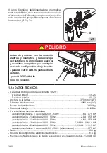
Страница 279: ...0mA montar fusibles de protección en la línea de alimentación de dimensiones conformes a las in dicaciones detalladas en la relativa placa de datos de la máquina Fig 1 conectar la máquina a una toma industrial no está permitida la conexión a tomas domésticas Asegurarse de que la presión disponible y las prestaciones de la instalación de aire comprimido sean compatibles con las que se requieren par...

Страница 280: ...dad de bloqueo del autocentrante 10 25 Desde el interior 13 25 Desde el exterior 10 22 Anchura de la llanta 370 mm 14 5 Diámetro máximo rueda 1060 mm 44 Fuerza de destalonadura 2900 Kg Presión de trabajo 8 10 Bar Caracteristicas tecnicas electricas version monofasica 1 velocidad 240V 50Hz 6A 0 75 kW version trifasica 1 velocidad 230V 50Hz 2 8A 0 55 kW version trifasica 1 velocidad 400V 50Hz 1 6A 0...

Страница 281: ... niveles de exposición permitidos también pueden variar de un país u otro De todos modos esta información permitirá al usuario de la máquina efectuar una mejor evaluación del peligro y del riesgo 1 2 f PRESIÓN DEL AIRE PELIGRO PELIGRO DE EXPLOSIÓN No superar la presión recomendada por el fabricante del neumático Hacer corresponder siempre las dimensiones del neumático y la llanta Prestaratenciónae...

Страница 282: ...sobre los peligros derivados del mantenimiento de dichas ruedas y los procedimientos de seguridad que deben respetar Por Servicio y Mantenimiento se entiende el montaje y el desmontaje de ruedas y todas las actividades relacionadas con las mismas como el inflado el desinflado la instalación la extracción y el desplazamiento El empleador debe asegurar que los operadores no intervengan en las ruedas...

Страница 283: ...ina A intervalos periódicos Después de reparaciones Se debe poner en marcha la máquina solo después de haber completado correctamente estos controles preliminares No usar la máquina si está fuera de servicio por puesta a punto mantenimiento lubricación etc 1 7 DURANTE EL USO En caso de percibir ruidos extraños o vibraciones inusuales si un componente o sistema no funciona correctamente o se observ...

Страница 284: ... 440 kg Versión TI 460 kg Condiciones del ambiente de transporte y almacenamiento de la máquina Temperatura 25 55 C ATENCIÓN Para evitar daños no superponer otros objetos sobre el embalaje Desplazamiento Para el desplazamiento del embalaje introducir las horquillas de una carretilla elevadora en las relativas ranuras ubicadas en la base del embalaje pallet Fig 3 Para el desplazamiento de la máquin...

Страница 285: ... pallet asegurarse de que se hayan retirado del mismo los siguientes elementos indicados a continuación Liberar la máquina de la parte superior del embalaje asegurarse de que no se haya da ñado durante el transporte y detectar los puntos de fijación al pallet La máquina se compone de 1 carcasa 2 cabezal 3 helper 4 dotación 5 depósitoaire soloenversiónT I 4 MONTAJE T I Version Introducirlabocadelde...

Страница 286: ... máquina en conformidad con todas las normas sobre la seguridad aplicables incluidas pero no limitadas a estas las emitidas por OSHA ADVERTENCIA IMPORTANTE para un uso correcto y seguro del equipo recomendamos un valor de iluminación del ambiente de al menos 300 lux ADVERTENCIA IMPORTANTE No instalar la máquina en lugares externos Está diseñada para el uso en ambientes cerrados y reparados PELIGRO...

Страница 287: ...IÓN Siempre que la máquina esté desconectada de la línea neumática durante largos períodos de tiempo antes de restablecer la alimentación neumática comprobar la configuración de los pedales de control como se muestra a continuación PELIGRO Antes de proceder con la conexión eléctrica y neumática y cada vez que se restablece la alimentación eléctrica y neumática comprobar que la máquina esté en la c...

Страница 288: ...bida en kW Hz Frecuencia en Hz Ph Número de las fases bar psi Presión de funcionamiento en bar y o psi Serial N El número de matrícula de la máquina ISO 9001 Certificación del Sistema de Calidad de la empresa CE Marca CE 6 1 POSICIÓN DEL OPERADOR En las figuras 9a se representan las posiciones ocupadas por el operador y las relativas zonas peligrosas P durante las diferentes fases de trabajo A Des...

Страница 289: ...Manual de uso 289 ES 7 DIMENSIONES mm Dimensiones embalaje vedi fig 10 Anchura 1200 1300 T I min 1710 max Profundidad 990 min 1360 max Altura 1890 min 2170 max B A H 10 ...

Страница 290: ...e alimentación 9 Brazo destalonador 10 Pala destalonadora 11 Soporte destalonador 18 Pedal para hincha tubeless 19 Manómetro 24 Cilindro de bajada torreta móvil 25 Cilindro de mando herramienta de desmontaje 28 Gancho de bloqueo del brazo 29 Brazo prensa talón 30 Herramienta prensa talón 31 Rodillo prensa talón 32 Brazo alza talón 33 Palanca alza talón 34 Tubo de conexión de aire 8 1 MANDOS 8 1 a ...

Страница 291: ...2 Pulsador subida bajada brazo vertical A subida B bajad a C bloqueado 23 Palanca de mando torreta 8 1 c PRENSA TALÓN 26 Válvula de mando subida bajada TPH 27 Válvula de mando de avance del disco TPH 8 1 d MANÓMETRO CON PULSADOR DE DESINFLADO 20 Pistola con manómetro 21 Pulsador para desinflar neumático 1 2 4 6 7 9 10 11 5 31 32 28 ...

Страница 292: ...características técnicas advertencias mantenimien to y cualquier otra información relativa al depósito del aire opcional el manual de uso y mantenimiento suministrado con la documentación del accesorio 22 23 21 20 26 27 33 3 8 14 13 15 12 18 19 25 24 29 30 34 ...

Страница 293: ...otencial de colisión con partes del cuerpo B A C P P ATENCIÓN EVITAR DAÑOS FÍSICOS Antes de realizar intervenciones de mantenimiento en la máquina 1 Colocar la máquina en una confi guración estable con el eje horizontal completamente atrás y la columna en posición de trabajo o de reposo 2 Desenchufar el cable de alimenta ción Fig 12a 3 Aislar la línea de aire comprimido desconectandolaválvuladecie...

Страница 294: ...tienen canal alguno Fig 13A Estas llantas no estánaprobadasporlasnormasdelDOT Department of Transportation Departamento de Transportes El acrónimo DOT certifica la conformidad de los neumáticos con las normas de seguridad adoptadas porEstadosUnidosyCanadá estasruedasnopueden venderse en estos mercados Ruedasdealtorendimiento curvaturaasimétrica Fig 13Balgunasruedaseuropeastienenllantascon curvatur...

Страница 295: ... completamente cerradas Fig 14 Desinflar completamente el neumático quitando el interior válvula Fig 14b Desinflar completamente el neumático extrayendo la válvula Regular el soporte de la llanta de acuerdo al diámetro de la rueda Regular la posición de la pala de acuerdo a la anchura de la rueda con el perno A fig 14a para lograr una mejor inclinación de la pala en el flanco del neumático en posi...

Страница 296: ...l pedal se invierte el moto de la paleta destalonadora Una vez liberados los talones retirar los an tiguos pesos de equilibrado Lubricar el neumático con cuidado a lo largo de toda la circunferencia del talón inferior y superior para facilitar el desmontaje y evitar que se dañen los talones fig 17 ATENCIÓN Pisar el pedal 3 C fig 16 que acciona el destalonador separar el talón y soltar el pedal Cua...

Страница 297: ... posición sin trabajo Pisarelpedal parallevarlacolumna a la posición sin trabajo La apertura y el cierre de las garras del auto centrante serealizanpisandosecuencialmente el pedal de mando Fig 18 Con las garras completamente cerradas presionar ligeramente el pedal de mando y co locarlo en la posición central Fig 18 En esta configuración se puede controlar la apertura de las garras cuando un hombre...

Страница 298: ... una medida levemente superior a la medida de la rueda apoyar la rueda en el plato autocentrante colocar el brazo prensa llanta en posición de trabajo Fig 20a accionar la válvula para presionar la rueda sobre el plato y bloquear la rueda con el pedal Nota Esta operación facilita la introducción de la cuña de la garra entre la goma y la llanta Fig 20a 20a 20 9 5 desmontaje DE LA RUEDA 9 5 a Posicio...

Страница 299: ...e de la llanta fig 22a ATENCIÓN Lograr la correcta posición ayudán dose con el puño 2 Fig 21a Presionar el mando de bloqueo 1 Fig 21a para fijar la posición de la herramienta La distancia entre la llanta e la herramienta se mantiene constante hasta que el mando está en posición de bloqueo El operador puede volcar libremente la columna vertical durante el montaje desmontaje de juegos deneumáticos s...

Страница 300: ...a rotación del autocentrante 24 1 2 1 25 9 5 c Desmontaje del talón superiore Verificar que la herramienta haya enganchado el talón del neumático Accionarelmando paraprepararseparalaposterioroperacióndedesmontaje esta operación debe ejecutarse con la máquina detenida nunca en rotación Fig 26 Controlar que no se haya reentalonado la parte del neumático próxima al operador Eventualmente ayudarse con...

Страница 301: ...operaciones accionar el pedal hasta lograr el desmontaje completo del talón Fig 28 28 9 5 d Desmontaje del talón inferior utilizando la torreta portaherramienta Pisar el pedal del autocentrante hasta que una garra se oriente hacia el operador y la flecha amarilla situada en el autocentrante se encuentre en dirección del disco TPH Fig 29a Bajar el brazo TPH hasta el fin de carrera utilizando el man...

Страница 302: ... TPH el brazo alza talón se deslizará hacia el centro del autocentrante hasta colocar el palpador en contacto con el borde inferior de la llanta Automáticamente el brazo alza talón se separará de la llanta unos 2 3mm Empujar el talón inferior con el disco alza talón utilizando el mando Accionar el garfio y enganchar el talón inferior del neumático B Fig 29c utilizando el mando ...

Страница 303: ...pedal para colocar la columna vertical en posición de reposo Pisar el pedal del autocentrante hasta que una garra se oriente hacia el operador y la flecha amarilla situada en el autocentrante se encuentre en dirección del disco TPH Bajar el brazo TPH hasta el fin de carrera utilizando el mando Levantar el neumático a la altura de la herramienta alza talón del TPH Accionando el mando situado en la ...

Страница 304: ...el completo des montaje del neumático D Fig 30 A B C D 30 9 5 f Desmontaje concluido Una vez concluido el desmontaje accionar el conmutador situado en la consola de mando del TPH para hacer retroceder la herramienta alza talón hasta su posición de reposo voltear la columna con el pedal de basculación columna y extraer el neumático Fig 31 31 ...

Страница 305: ...te Comprobar también que las llantas no estén deformadas que sus orificios de fijación no estén ovalados que no estén incrustados ni oxidados y que no tengan rebabas afiladas en los orificios de la válvula Comprobar que el neumático esté en buenas condiciones y que no haya daños 9 6 a Preparación del neumático Engrasar ambos talones del neumático Fig 32 Posicionar el neumático en la llanta Fig 32a...

Страница 306: ...mático no deslice bajo la herramienta 9 6 e Posicionamiento del rodillo prensa talón Acercar el rodillo prensa talón al borde de la llanta 2 3mm y bloquear su posición enroscando el pomo Fig 33a Bajar el rodillo prensa talón mando hasta el nivel del canal de la llanta Fig 33b 2 1 33a 33b 9 6 f Montaje del talón superior Activar la rotación pedal para montar el talón Presionar manualmente el neumát...

Страница 307: ...el neumático consiguiendo de mantener el segundo talón dentro del canal sin esfuerzo o riesgos para el operador 34a 34b ATENCIÓN Cuando el dispositivo prensa talón llega en posición de 6 horas reducir la presión del dispositivo sobre el neumático mando 26 para evitar provocar danos al talón Cuandosecompletaelmontaje levantarelprensa talónyelrodillo comando Colocar la torreta de la herramienta en p...

Страница 308: ...l canal ejerciendo una presión en la posición de las 3 horas Reiniciar la rotación hasta montar completamente el neumático Quitar la mordaza el prensa talón la herramienta y el rodillo prensa talón Llevar el grupo prensa talón y el rodillo a la posición de reposo 9 7 EL INFLADO DE LOS PNEUMÁTICOS 9 7 a Indicaciones de seguridad PELIGRO PELIGRO DE EXPLOSIÓN No superar la presión recomendada por el ...

Страница 309: ...ivamente inflados pueden explotar causando la dispersión en el aire de detritos que pueden provocar accidentes 2 Los neumáticos y llantas que no tienen el mismo diámetro se consideran no corres pondientes No intentar montar ni inflar neumáticos con llantas no correspondientes Por ejemplo no montar nunca un neumático de 16 en una llanta de 16 5 y vicever sa Es muy peligroso Los neumáticos y llantas...

Страница 310: ...n recomendada por el fabricante del neumático Ladesmontadoradeneumáticosnoesundispositivodeseguridadynoevitarála explosióndeneumáticosyllantas Manteneradistanciaalaspersonaspresentes 9 7 b INFLADO DE LOS NEUMÁTICOS Asegurarse de que la rueda NO esté bloqueada en el autocentrante me diantelasgarrasdecentrado Fig 35 Llevar el brazo horizontal al centro delarueda completamenteextraí do hacia el opera...

Страница 311: ... sección correspondiente lubricar y girar el neumático sobre la llanta Repetir la operación de montaje anteriormente ilustrada y efectuar una ulterior verificación 37 38 39 ATENCIÓN Peligro de explosión Durante la fase de inserción del talón no sobrepasar la presión máxima indicada por el fabricante en el flanco del neumático Una vez efectuada la inserción del talón volver a montar la parte intern...

Страница 312: ...te desde la parte interna fig 40 Introducir el cono de centrado en el brazo prensa llanta colocarelbrazoenposicióndetrabajo accionar el mando 16 hasta que el cono entre en contacto con la llanta fig 36 Quitar el núcleo de la válvula en caso de que no haya sido extraído Fig 37 Conectar la conexión Doyfe del tubo de inflado al vástago de la válvula Fig 38 Pisar a fondo brevemente el pedal de inflado...

Страница 313: ...ta que no pre senten el mismo diámetro por ejemplo neumático de 16 pulgadas y 1 2 con una llanta de 16 pulgadas En el caso en que el neumático esté inflado excesivamente es posible purgar el aire presionando el pulsador manual de desinflado de latón ubicado debajo del manómetro de la presión de aire Fig 43 Desconectar el tubo de inflado del vástago de la válvula Llevarlosbrazosoperativoshastalapos...

Страница 314: ...las conexiones del cable en el enchufe El motor no gira Controlar los microinterruptores de los pedales solo para motor inversor Controlar el mando rotación motor de los pedales Sustituir la tarjeta inversor solo para motor inversor Sustituir motor La correa está rota Remplazar la correa Reductor bloqueado Sustituir el reductor Autocentrante no gira en un sentido o en otro Mando defectuoso Sustitu...

Страница 315: ...iado de la llanta Placa bloqueo no regulada Regular placa Columna no abre Cilindro de apertura columna averiado Sustituir el cilindro de apertura columna No llega aire al cilindro Tubos doblados Sustituir la válvula Los cilindros de bloqueo del brazo pierden aire Pistón o juntas defectuosas Sustituir pistones y juntas La columna abre de modo violento o demasiado lentamente Reguladores de descarga ...

Страница 316: ...o de mantenimiento o ordinario o rellenado de lubricante desconectar la máquina de la línea de alimentación neumática ATENCIÓN El fabricante declina cualquier responsabilidad en caso de reclamaciones que deriven del uso de accesorios de recambio no originales Limpiar regularmente la máquina de la suciedad Mantener todas las guías limpias y lubricadas eje vertical horizontal guías garras El grupo f...

Страница 317: ...do del agua por lo que en condiciones normales de uso no requiere ningún tipo de mantenimiento particular de todos modos es posible realizar en cualquier momento un drenaje manual fig 47d Normalmente no es necesario desmontar las copas pero para las operaciones de mantenimiento después de largos períodos de uso esta necesidad puede ocurrir si no fuera suficiente el uso de las manos utilizar la lla...

Страница 318: ...ORMACIÓN MEDIOAMBIENTAL Elsiguienteprocedimientodeeliminaciónsedebeaplicarexclusivamentealasmáquinas donde la placa de datos de la misma presenta el símbolo del contenedor tachado Este producto puede contener sustancias que pueden ser dañinas para el medio am biente y para la salud humana si no se elimina de manera correcta Por lo tanto suministramos la siguiente información para evitar la liberac...

Страница 319: ...da de todos se puede reducir la cantidad de recursos naturales empleados para la realización de equipos eléctricos y electrónicos minimizar el uso de vertederos para la eliminación de los productos y mejorar la calidad de la vida evitando que sus tancias potencialmente peligrosas se liberen en el ambiente 14 INDICACIONES Y ADVERTENCIAS SOBRE EL ACEITE Eliminación aceite usado No verter el aceite u...

Страница 320: ...ire libre y luego al ambulatorio Ojos mojarabundantementeconaguaydirigirselomásrápidoposibleauncentrosanitario Piel lavar con agua y jabón 15 MEDIDAS DE PREVENCIÓN DE INCENDIOS UTILIZABLES Para elegir el extintor más adecuado consultar la siguiente tabla 15 1 Materiales secos Hídrico SÍ Espuma SÍ Polvo SÍ CO2 SÍ 15 2 Líquidos inflamables Hídrico NO Espuma SÍ Polvo SÍ CO2 SÍ 15 3 Equipos eléctricos...

Страница 321: ... a la abrasión y agarre en condiciones secas y húmedas así como condiciones de funcionamiento silenciosas 2 Borde o refuerzo Se trata de un inserto de metal o tejido colocado en la parte exterior del talón para evitar que las telas de la carcasa rocen contra la llanta 3 Carcasa Constituye la estructura resistente y está compuesta por una o más capas de lona engomada La disposición de las capas que...

Страница 322: ...a parte superior del talón y se utiliza como referencia para comprobar el correcto centradodelneumáticoenlallantadespuésdelmontaje 7 Bordillodeprotección Esunrelievecircunferencial situado en la zona del lateral más expuesto al deslizamiento accidental 8 Lateral Esta es el área entre el balcón y el bordillo de centrado Consiste en una capa de caucho de diferentes espesores diseñada para proteger l...

Страница 323: ...esurizado contenido en la carcasa Este tipo de neumático debe montarse en llantas específicas directamente sobre las que está fijada la válvula II Llanta Rueda La llanta es el elemento metálico rígido que conecta el cubo del vehículo con el neumático de forma fija pero no permanente Perfil de la llanta El perfil de la llanta es la forma de la sección en contacto con el neumático Está realizado con...

Страница 324: ... neumáticos tubeless Entalonado Esta operación se obtiene durante la fase de inflado y garantiza un centrado perfecto entre el talón y el borde de la llanta Pinza prensa talón Esta herramienta está destinada a ser utilizada para el montaje del talón superior Se coloca de forma que se enganche al balcón de la llanta y mantenga el talón superior del neumático dentro del canal Normalmenteseutilizapar...

Страница 325: ...11 12 x 9 10 x 7 8 x 5 6 x 3 4 x 1 2 L 0 R 1 2 3 L1 ELEMENTI Elements CONTATTI Contacts W2 U1 U2 V2 V1 W1 W2 U1 U2 V2 V1 W1 200 220 240V 380 415 440V MORSETTIERA Junction Box F F F Power Phase 400V 3 50 Hz 0 55 kW 500V 4A 400V 3 50 Hz 0 75 kW 500V 6A 230V 3 50 Hz 0 55 kW 250V 10A 230V 3 50 Hz 0 75 kW 250V 10A 200V 3 50 Hz 0 75 kW Japan 250V 10A F Fuse TYRE CHANGER 1 SPEED VERSION 3 PHASE ...

Страница 326: ...1 12 x 9 10 x 7 8 x 5 6 x 3 4 x 1 2 L 0 R 1 2 3 ELEMENTI Elements CONTATTI Contacts F F Power Phase Neutral 230V 1 50 Hz 250V 16A 250V 16A 240V 1 50 Hz 250V 16A 250V 16A 220V 1 60 Hz 250V 16A 250V 16A 115V 1 60 Hz 250V 20A 250V 20A F Fuse W2 U1 U2 V2 V1 W1 C 3 2 8 12 MORSETTIERA Junction Box AUTOMATIC TYRE CHANGER version TYRE CHANGER 1 SPEED VERSION 1 PHASE ...

Страница 327: ... 1 3 5 7 9 11 2 4 6 8 10 12 13 15 17 19 21 23 14 16 18 20 22 24 L2 23 24 x x x 21 22 x 19 20 x 17 18 x x 15 16 x x 13 14 x 11 12 x 9 10 x 7 8 x x 5 6 x x 3 4 x 1 2 L2 L1 0 R 1 2 3 4 5 6 V2 U2 W2 W1 V1 U1 PE 22 13 15 24 9 11 F F F Power Phase 400V 3 50 Hz 500V 6A 230V 3 50 Hz 250V 16A 400V 3 60 Hz 500V 6A 230V 3 60 Hz 250V 12A F Fuse TYRE CHANGER 2 SPEED VERSION 3 PHASE ...

Страница 328: ...GER MOTOINVERTER VERSION AP1 N PE L1 F F XS1 L1 N SQ3 XB1 SQ1 SQ2 M1 R T S 1 2 3 4 U V W MARRONE NERO AZZURRO GRUPPO MOTORE MOTOR UNIT GRUPPO COMANDI CONTROL SWITCH Power Phase Neutral 200 230V 1 50 60 Hz 250V 12A 250V 12A F Fuse ...

Страница 329: ...Manual de uso 329 ES 18 ESQUEMA INSTALACIÓN NEUMÁTICA P max 12 bar 33 32 31 30 29 28 1 2 4 3 5 6 7 8 9 10 11 12 12 13 13 15 14 34 35 36 16 17 19 18 20 21 22 23 24 25 27 26 H G F E D N L M I A B C ...

Страница 330: ...e standards and Directi ves mentioned above valid only for EC marked machines Fra Déclarons que le materiel objet de cette déclaration dont nous avons élaboré le livret tech nique restant en notre possossion est conforme aux normes et Directives susmentionnèes valable uniquement pour le machines avec marquage CE Deu Erklärt hiermit dass das product Worauf sich die vorliegende Erklärung bezieht und...

Отзывы: