4-41
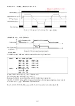
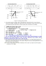
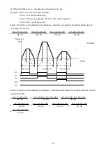
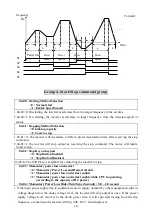
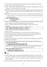
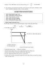
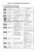
2. The heat sinking function will not be as effective when the motor run at low speed. So the
thermal relay action level will decline at the same time. (The curve 1 will change to curve 2).
3. 07-06 = 0: Set 06-04 as the rated frequency of the serve motor.
4. 07-08 = 0: the inverter coast to stop as the thermal relay acts and flash OL1. Press the
‘Reset’ or the external reset terminal to continue to run
= 1: the inverter continues to run as the thermal relay acts and flash OL1. Until the
current decline to 103% or 113 %( determined by 9-10), OL1 will disappear.
Minute
(1)
(2)
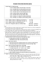
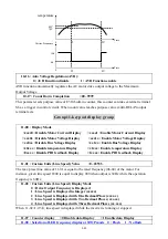
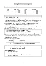
07-09 : Over torque Detection Selection(OL3)
= 0 : Disable Over torque Operation
= 1 : Enable Over torque Operation Only if at Set Frequency
= 2 : Enable Over torque Operation while the Drive is in Run Mode
07-10 : Operation After Over torque Detection is Activated
= 0 : Coast-to-Stop After Over torque is Activated
= 1 : Drive will Continue to Operate After Over torque is Activated
07-11 : Over torque Threshold Level(%) : 30
~
300
07-12 : Over torque Activation Delay Time (S) : 0.0
~
25.0
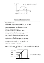
1. Over Torque is detected when the output torque level exceeds the level set in
Parameter 07-11 ( Inverter rated torque is 100%) and if it is detected for a duration of time
which is set in parameter 07-12.
2. 07-10
=0 : If there is over torque, the inverter coasts to stop and flashes OL3. It is necessary to
press’RESET’ or external terminal to continue to run.
=1 : If there is over torque, the inverter can continue to run and flashes OL3 until the output
torque is less than the 07-11 set value.
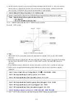
3. Parameter 01-09/10(Multifunction output terminal) = 12, the output terminal signal will be set
for over torque condition.
Note:
Over torque detection will be enabled only when parameter 07-09 is set to options 1or2.
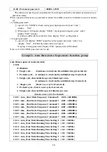
07-13 : OH over heat Protection ( cooling fan control)
0 : Auto (Depends on temp.)
1 : Operate while in RUN mode
2 : Always Run
3 : Disabled
1. 07-13=0 : The fan runs as the inverter senses temperature rises. Thusly, extend the service period.
2. 07-13=1 : The fan runs while the inverter is running.
3. 07-13=2 : The fan is continuously running regardless of the action of the inverter.
4. 07-13=3 : The fan is
Disabled.
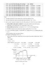
07-15 Current Limit Protection =0 :
Enable
=1 :
Disable
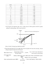
Current limit protection is the function to protect the inverter by limit the output current of inverter,
if 07-15=0, when the load is very heavy or the acceleration time is very short, the inverter may be
trip by OC (Over current). So, please keep 07-15=1 (Current limit protection is enable), to maintain
the inverter running smoothly.
Current Percen
t
150
1.0

