background image


Basic documentation 


TXV 172 52 

6.  OPERATION  

6.1  MODULE CONFIGURATION  

The module is operated, set and diagnosed from the MOSAIC development environment.   


6.2  PUTTING IN OPERATION  

After putting the module into the rack and switching power supply on, the module is ready for 

its  activity.  The  set-up  procedure  is  described  in  documentation  TXV  004  24.  Other  activities 

(set-up, programming, etc.) are carried out in the MOSAIC development environment. 


7.  DIAGNOSTICS 

The  basic  diagnostic  system  of  the  module  is  part  of  the  standard  module  software.  The 

diagnostic system becomes active after module power supply is on, and works independently 

from the user. The error states of the module are available for processing by a superior system. 

Detailed information can be found in documentation TXV 004 24.  


8.  MAINTENANCE AND CLEANING 

When  following  general  installation  instructions,  the  module  does  not  require  any  other 

maintenance.  Should  dismantling  of  some  part  of  the  module  be  necessary,  supply  voltage 

must always be OFF.  

Since the module contains semiconductor components, it is necessary to follow the principles 

for  working  with  components  sensitive  to  electrostatic  charges  when  handling  the  cover  taken 
off. It is strictly prohibited to touch printed circuits directly without protective measures!!!


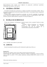
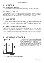
9.  SUB-MODULE INSTALLATION  

The place for sub-module installation is available 

after  removing  the  module  outside  the  rack  and 

opening the window at the side of the module. 

A  detailed  procedure  of  manipulation  with 

interface sub-modules and other information can be 

found  in  documentation  TXV  004  02,  chapter  2.3 

and in documentation of particular sub-modules. 


Fig. 9.1: Location of communication sub-modules 


CHx+1 

CHx 

Содержание CD-7252

Страница 1: ...D INFO lze ji tak objednat v ti t n podob n zev Moduly d lkov ch p enos TC700 obj slo TXV 004 24 Dokumentace je tak k dispozici on line na www tecomat cz Detailed user documentation is available on an...

Страница 2: ...da vlivu prost ed SN 33 2000 3 Norm ln Rozsah provozn ch teplot 0 C a 55 C Povolen teplota p i p eprav 25 C a 70 C Relativn vlhkost vzduchu 10 a 95 bez kondenzace Atmosf rick tlak min 70 kPa 3000 m n...

Страница 3: ...lota je 20 C 3 MONT Instalace modulu do nosn ho r mu syst mu TC700 se prov d dle TXV 004 02 Mechanick rozm ry jsou uvedeny v dokumentaci TXV 004 02 4 NAP JEN Modul je nap jen z nap jec ho zdroje kter...

Страница 4: ...e p mo dot kat plo n ch spoj bez ochrann ch opat en 9 INSTALACE SUBMODUL Prostor pro submoduly je p stupn po vyjmut modulu z r mu a otev en ok nka na boku modulu Podrobn postup manipulace se submoduly...

Страница 5: ...x 30 x 198 mm 1 2 OPERATIONAL CONDITIONS Class of ambient influence SN 33 2000 3 normal Operating temperatures range 0 C to 55 C Permissible temperatures during transport 25 C to 70 C Relative humidi...

Страница 6: ...atmospheric actions Transportation of the product is permitted within a temperature range of 25 C to 70 C relative humidity of 10 to 95 without condensation and minimum atmospheric pressure higher tha...

Страница 7: ...e found in documentation TXV 004 24 8 MAINTENANCE AND CLEANING When following general installation instructions the module does not require any other maintenance Should dismantling of some part of the...

Страница 8: ...mentation The system must not be put in operation if it is not verified and confirmed that the equipment in which the TC700 system is part of it meets the requirements of the directive 89 392 CEE if t...

Отзывы: