5
L’installazione all’esterno è permessa solo se il refrigerante utilizzato è un antigelo (glicole etilenico) Durante
il montaggio considerare le caratteristiche di funzionamento dell’attuatore dell’unità di miscelazione. Durante
il montaggio del refrigeratore, scambiatore di calore, vaschetta di scarico e tubo di scarico si smontano in modo
semplice e veloce.
Il refrigeratore è progettato per l’installazione orizzontale per permettere il drenaggio della condensa. Fornire accesso
sufficiente per le operazioni di manutenzione e riparazione durante il montaggio. Il refrigeratore può essere installato
sopra e sotto l’unità di ventilazione. Se il refrigeratore è installato sotto al ventilatore, fornire un condotto dell’aria
di almeno 1/1,5 m tra il refrigeratore e il ventilatore per stabilizzare il flusso dell’aria. Prima di iniziare il montaggio,
controllare le condizioni del tubo, delle piastre e del collettore tubolare. Le flange dei componenti del sistema sono
montate con bulloni zincati e dadi M8. Prima dell’avvio e dopo un lungo periodo di fermo macchina, riempire il sifone
di acqua. L’unità di alimentazione/trattamento aria può essere dotata di sifone e valvola a sfera, specie per le unità
con pressione negativa. Questo sifone non va riempito di acqua.
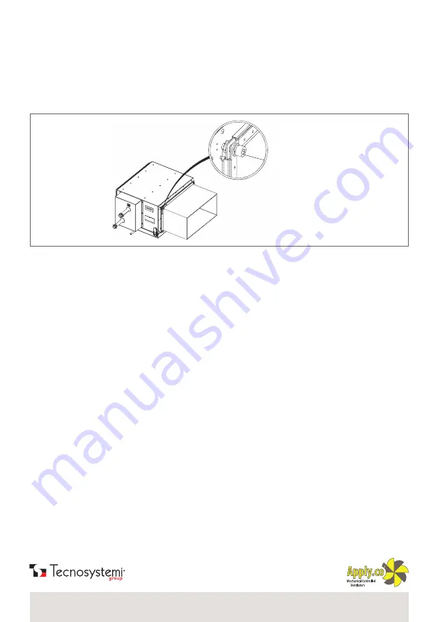
Il refrigeratore è collegato al condotto dell’aria con una connessione a flangia, fig.4.
MONTAGGIO E CONFIGURAZIONE
/ ASSEMBLY AND CONFIGURATION
fig. 4
/ pic. 4
The chiller is connected to the air duct with a flange connection, shown in fig.4.
Outdoor installation is allowed only if the coolant used is an anti-freeze (ethylene glycol). During assembly, consider the
operating characteristics of the mixing unit actuator. When assembling the chiller, the heat exchanger, discharge tray and
drain hose can be disassembled quickly and easily.
The chiller is designed for horizontal installation to allow for condensate drainage. During assembly, leave enough space for
maintenance operations and repairs. The chiller can be installed above and below the ventilation unit. If the chiller is installed
below the fan, provide an air duct of at least 1/1.5 m between the chiller and the fan to stabilise the air flow. Before starting
assembly, check the conditions of the hose, plates and tube manifold. The flanges of the system components are mounted
using galvanised bolts and M8 nuts. Before start-up and after a long period of inactivity, fill the siphon with water. The air
supply/treatment unit can be equipped with a siphon and ball valve, especially for negative pressure units. This siphon must
not be filled with water.


