


Mounting Instructions
II_StraightBolt_02_eng Page 3 of 4
and will void the manufacturer’s warranty and Standard approvals.
•
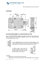
Entry unit cable hole on the safe door does not have to exceed 12 mm
diameter.
•
Use of screw locking glue (i.e. Loctite) is recommended.
•
No through holes on the safe door are allowed within the lock body area
beside the spindle/cable hole.
•
Lock body area should be protected against destructive attacks.
•
Lock has to be mounted on secure storage metal (preferred steel) units
only.
•
Security relevant parts of a HSL should not be accessible to unauthorized
persons when the door of the secure storage unit to which it is fitted is
open.
DO NOT OVER TORQUE MOUNTING SCREWS.
Mount the entry unit following the manufacturer’s instruction.
The grooved shaft must extend between 10 and 15 mm
off the mounting surface. Make sure the cable is in the
groove.
Insert the cable connector into the square hole in the
bottom of the lock and guide it through the hole in the
lock cover. Holding the cable straight place the lock with
the square cavity on the grooved shaft and then screw it
to the mounting surface.
Insert the connector of the entry unit in the outer
position. Check that the connector is completely seated.
(To remove the connector, lift it up and carefully pull it
out.)
To tie the cable, push it into the square groove in the lock cover.
MOUNTING INSTRUCTION
In the LOCKED position the distance between the StraightBolt lock bolt and the boltwork part that is moving
the lock bolt should be approximately 1 mm.
Only use NL LOCK supplied screws (M6) to mount the lock. Lock has to be mounted on secure storage metal
(preferred steel) units only. Tighten the screws securely so the lock body is attached firmly to the mounting
surface. Use of screw locking glue (i.e. Loctite) is recommended.
Security relevant parts of a HSL should not be accessible to unauthorized persons when the door of the
secure storage unit to which it is fitted is open
Test Electronics
Like all locks from NL LOCK this unit includes a unique feature to functionally test the electronics:
Function #5
Functional Test
•
Enter code (i.e. 1-2-3-4-5-6). The lock emits a double signal for the correct code.
•
Turn Entry unit clockwise until stop. Lock bolt must move freely. Boltwork/door can be opened.
•
Turn handle towards Locked position. Turn Entry unit counter-clockwise until stop. The lock bolt
must fully extend and secure.
•
Make sure there is an air space on all sides of the lock bolt when the safe’s boltwork is fully thrown
into locked position.
IMPORTANT: Perform the functional test several times before locking the safe door.
EM35•20 Technical Manual rev. 160223
© 2016 Lock Technology Page
!
of
!
2
2
STEP
TASK
REMARK
1
Press and hold [5] until a double
signal sounds and the light stays ON.
2
Enter the all keys in exactly this
sequence:
[1]-[2]-[3]-[4]-[5]-[6]-[7]-[8]-[9]-[0]
Push buttons slowly so you recognize the signaling of the
lock. A double signal indicates that the keypad and the lock
communicate and perform properly.
A long signal indicates that the electronics may be damaged.
Insert the connector of the entry unit in the outer position. Check
that the connector is completely seated. (To remove the
connector, lift it up and carefully pull it out.)
To tie the cable, push it into the square groove in the lock cover.
The grooved shaft must extend between 10 and 15 mm off the mounting
surface. Make sure the cable is in the groove.
Insert the cable connector into the square hole in the bottom of the lock
and guide it through the hole in the lock cover. Holding the cable straight
place the lock with the square cavity on the grooved shaft and then screw
the lock to the mounting surface.
In the entry unit or battery box, connect a 9V-ALKALINE-battery from a brand
name manufacturer, e.g. DURACELL.
A series of signals during opening
indicates that the battery is weak and must be replaced.
FUNCTIONAL TEST
(with door open)
A.
Test Electronics
Press and hold [5] until a double signal sounds and the light stays ON.
Enter the all keys in exactly this sequence:
[1]-[2]-[3]-[4]-[5]-[6]-[7]-[8]-[9]-[0]
Push buttons slowly so you recognize the signaling of the lock. A double signal
indicates that the keypad and the lock communicate properly.
A long signal indicates that the electronics may be damaged.


