


©
Technosoft 2022
47
iPOS4803 Microdrive EtherCAT Technical Reference
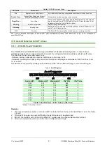
Table 3.
ERROR Indicator States
ERR state
Error name
Description
On
Application controller failure
An critical communication or application controller error has occurred
Double Flash
Process Data Watchdog Timeout/
EtherCAT Watchdog Timeout
An application watchdog timeout has occurred.
Single Flash
Local Error
Slave device application has changed the EtherCAT state autonomously,
due to local error (see ETG.1000 part 6 EtherCAT State Machine). Error
Indicator bit is set to 1 in AL Status register.
Blinking
Invalid Configuration
General Configuration Error
Flickering
Booting Error
Booting Error was detected. INIT state reached, but Error Indicator bit is
set to 1 in AL Status register
Off
No error
The EtherCAT communication of the device is in working condition
For a more detailed description of EtherCAT® LED functionalities please read ETG.1300 S (R) V1.0.1 available at
www.EtherCAT.org
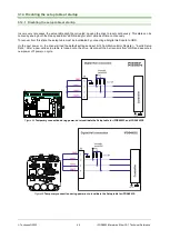
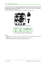
3.16 Axis ID Selection for CAT drives
3.16.1 iPOS4803P and iPOS4803PE
The iPOS4803P and iPOS4803PE drives support all EtherCAT standard addressing modes. In case of device
addressing mode based on node address, the drive sets the
configured station alias
address with its AxisID value.
The drive AxisID value is set after power on by:
- Software, setting via EasySetUp a specific AxisID value in the range 1-255.
- Hardware, by setting h/w in Easy setup under Axis ID value and selecting a value between 1-255 from the J1 pins
10, 21 and 22.
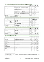
The AxisID is set by providing a voltage to the AxisID pins (ID0, ID1 and ID2) according to
Table 4-
AxisID Register
Nominal[V]
Minimum[V]
Maximum[V]
IDx* Bits
IDx* Value
0.000
0.00
0.51
000
0
1.016
0.51
1.35
001
1
1.689
1.35
1.93
010
2
2.167
1.93
2.33
011
3
2.500
2.33
2.64
100
4
2.783
2.64
2.90
101
5
3.008
2.90
3.10
110
6
3.192
3.10
3.30
111
7
AxisID = 64*(ID2 Value) + 8*(ID1 Value) + (ID0 Value)
*where ”x” can be 1, 2 or 3
Remarks:
1. The drive axis/address number is set when H/W is selected in Drive Setup under AxisID field or when the Setup
is invalid.
2.
If the AxisID pins are not connected (floating) the AxisID value can’t be determined.
3. If Bit 8=1 the AxisID is set to 255 and the EtherCA
T register called “configured station alias” will be 0.
4. All pins are sampled at power-up, and the drive is configured accordingly.