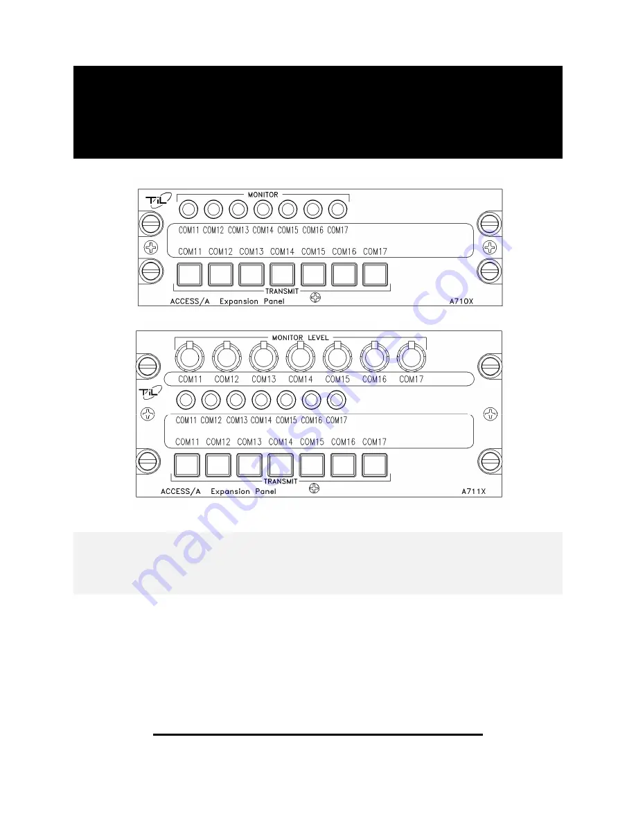
Technisonic Industries Limited ACCESS/A A710X Скачать руководство пользователя страница 1

ACCESS/A

TM    

EXPANSION PANEL  

MODELS:   A710X & A711X 


Installation and  

 Operating 

Instructions


TiL Document No. 

 06RE387 

rev-A 


April  2007


Technisonic Industries Limited 


240 Traders Blvd. E., Mississauga, Ontario L4Z 1W7  Tel:(905)890-2113  Fax:(905)890-5338 

www.til.ca


Содержание ACCESS/A A710X

Страница 1: ...L MODELS A710X A711X Installation and Operating Instructions TiL Document No 06RE387 rev A April 2007 Technisonic Industries Limited 240 Traders Blvd E Mississauga Ontario L4Z 1W7 Tel 905 890 2113 Fax...

Страница 2: ...87 rev B Technisonic Industries ltd Copyright 2007 BY TiL ALL RIGHTS RESERVED ii REVISIONS Revision Page Description Date Approved A 1 2 compliance reference changed Jun 21 2007 RKD from TSO C50c to T...

Страница 3: ...14228 Tel 905 890 2113 Tel 716 691 0669 Fax 905 890 5338 TRADEMARK INFORMATION ACCESS A ACCESS D ACCESS R ACCESS F are all trademarks of Technisonic Industries Ltd and Sphere Research Corporation All...

Страница 4: ...g Requirements 2 1 2 4 Expansion Panel Installation Drawings 2 1 Cable Clearance 2 2 Panel Modifications 2 2 Shield Grounds 2 2 Internal Options 2 2 2 5 Installation Kit Contents 2 8 2 6 Pin Locations...

Страница 5: ...View 1 3 1 2 A711X Expansion Panel General View 1 4 2 1A A710X Outline Drawing 2 3 2 1B A711X Outline Drawing 2 4 2 2 System Installation Drawings COM11 COM14 Wiring 2 5 2 3 System Installation Drawin...

Страница 6: ...io Controller Seven transceivers can be connected to the expansion panel and selected in the same manner as a standard A710 or A711 audio controller The Expansion Panel is connected to an A710 or A711...

Страница 7: ...act Requirements The A710X and A711X are compliant with TSO C139 The units meet RTCA DO 214 and RTCA DO 160C applicable categories with the exception of the RF Susceptibility Test which is based upon...

Страница 8: ...CESS A A710X A711X Installation Operating Instructions 06RE387 rev B Technisonic Industries ltd Copyright 2007 BY TiL ALL RIGHTS RESERVED Page 1 3 FIGURE 1 1 A710X ACCESS A EXPANSION PANEL GENERAL VIE...

Страница 9: ...CESS A A710X A711X Installation Operating Instructions 06RE387 rev B Technisonic Industries ltd Copyright 2007 BY TiL ALL RIGHTS RESERVED Page 1 4 FIGURE 1 2 A711X ACCESS A EXPANSION PANEL GENERAL VIE...

Страница 10: ...ICS Width max 5 75 inches Height max 1 875 inches Depth 6 07 inches Weight 1 4lbs 0 64Kg Mounting Standard Dzus 4 fasteners POWER SOURCE REQUIREMENTS DC Voltage MIN TYPICAL MAX 20 0V 28 V 32 2V DC Cur...

Страница 11: ...ing Standard Dzus 4 fasteners POWER SOURCE REQUIREMENTS DC Voltage MIN TYPICAL MAX 20 0V 28 V 32 2V DC Current 20 mA Backlighting Input Standard 28 Vdc 70 mA Optional 5 Vdc 370 mA TECHNICAL CHARACTERI...

Страница 12: ...llation and Operating Instructions chapter 2 describes shield terminations for minimum ground loop noise The test harnesses used for RTCA DO 160 sections 19 20 and 21 Induced Signal Susceptibility RF...

Страница 13: ...Heatshrink solder sleeves such as Raychem or equivalent should be utilized for shield termination All audio input and output line connections should be made with 2 conductor twisted pair shielded cab...

Страница 14: ...low cost in the field with no special tools or service facilities required SHIELD GROUNDS Convenient shield ground connections are provided at each connector for the indicated input signal shield dra...

Страница 15: ...A710X A711X Installation Operating Instructions 06RE387 rev B Technisonic Industries ltd Copyright 2007 BY TiL ALL RIGHTS RESERVED Page 2 3 FIGURE 2 1A Outline Drawing for Model A710X ACCESS A Expansi...

Страница 16: ...A710X A711X Installation Operating Instructions 06RE387 rev B Technisonic Industries ltd Copyright 2007 BY TiL ALL RIGHTS RESERVED Page 2 4 FIGURE 2 1B Outline Drawing for Model A711X ACCESS A Expansi...

Страница 17: ...tries ltd Copyright 2007 BY TiL ALL RIGHTS RESERVED Page 2 5 Shields are grounded as required at either end of the cables Do not ground both ends of a shield Mic Key Lo lines may be run as a 3 cond sh...

Страница 18: ...tries ltd Copyright 2007 BY TiL ALL RIGHTS RESERVED Page 2 6 Shields are grounded as required at either end of the cables Do not ground both ends of a shield Mic Key Lo lines may be run as a 3 cond sh...

Страница 19: ...td Copyright 2007 BY TiL ALL RIGHTS RESERVED Page 2 7 Shields are grounded as required at either end of the cables Do not ground both ends of a shield Mic Key Lo lines may be run as a 3 cond shielded...

Страница 20: ...or complete with crimp pins V locks and hood DD50S P101 Positronics p n SD50F00JVLX 50ea FC7520D contacts 2 One 37 pin female D subminiature mating connector complete with crimp pins V locks and hood...

Страница 21: ...8VDC Power In Main Power Input 34 Power GROUND Main Power Ground Line 1 Lighting Dimmer Common GND Dimmer Lines 2 5 VDC Dimmer Input Dimmer Lines Use only one 3 28 VDC Dimmer Input Dimmer Lines Use on...

Страница 22: ...UM Out To Audio Panel RX COM channel 4 Shield ground Shield drain for input lines 31 13 COM 7 RX Audio Right hand most TX switch 32 14 COM 6 RX Audio 33 15 COM 5 RX Audio 34 16 COM 4 RX Audio 35 17 CO...

Страница 23: ...g and there is a dedicated lighting ground pin which MUST be connected for the lighting to work Lighting is isolated from other circuits in the system for noise reduction reasons 2 9 GROUND The A710X...

Страница 24: ...and are either variable rotating controls or selectable push button switches The exact radio legends on the face of the A710X or A711X may vary from the illustration shown due to customer specificatio...

Страница 25: ...e setting of the TX SELECTOR switches determines which Transceiver will transmit the activated microphone audio and which receiver the system will monitor independent of the additional RX switch setti...

Страница 26: ...ntrols are provided to adjust the level for each of the 7 transceivers These controls normally go to approximately 2 5 level at the minimum setting not off but can be strapped internally to go fully o...

Страница 27: ...M NODE This line is used to expand the RX input bus of the A710 A711 control and allows many supplemental receivers to be attached with high isolation from other signals Use of either the A710X or A71...

Страница 28: ...all polarized square plug on the rear mates with the lighting assembly and can be pulled off to allow the overlay to be completely removed and exchanged If the lighting VOLTAGE is changed the overlay...

Отзывы: