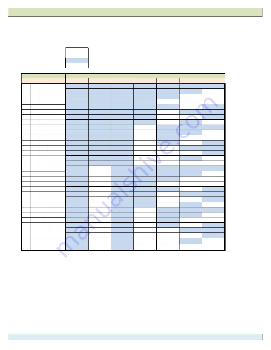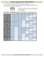
1. The 5 pairs of pads on the bottom side of the PCB selects which functions are turned off or on.
2. There is a small trace connecting the upper pads to the lower pads respectively. Resulting in a total of 5 jumpers.
4. Refer to the following table to select the desired function(s) and perform the necessary cut or soldering before installing.
5. If you are going to install all features. Do not cut anything.
=
Leave pads shorted together / If cut already, then solder pads together
X
=
Cut trace between pads / If soldered, remove solder between pads
=
Functions are available
=
Functions not available
Functions Chart
16
8
4
2
1
OFF
Parking
Lights
High Beam
Fog
Emergency
Strobe
X
X
X
X
X
X
X
X
X
X
X
X
X
X
X
X
X
X
X
X
X
X
X
X
X
X
X
X
X
X
X
X
X
X
X
X
X
X
X
X
X
X
X
X
X
X
X
X
X
X
X
X
X
X
X
X
X
X
X
X
X
X
X
X
X
X
X
X
X
X
X
X
X
X
X
X
X
X
X
X
Functions Configuration Chart - MODEl: ONE64LED
www.technickldesigns.com - MODEl: ONE64LED Rev 1.4
Jumper Pads


