

3.4
Display (optional)
3.5
Cardboard stand (optional)
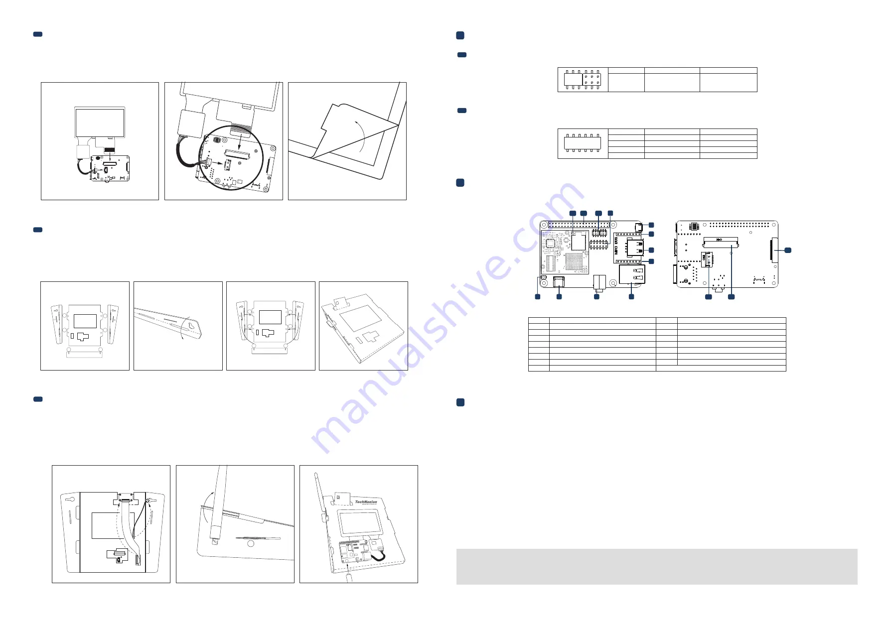
5
External Connectors
4
Pin Definition
Please follow the steps below to properly install the display.
Step 1: Locate the TOUCH and MIPI Display FPC connectors on the development board. Swivel the black retaining clips upward.
Step 2: Insert ends of the TOUCH and MIPI Display FPC cables into the connectors on the board. The silver pins on the FPC cable should be facing down. Then swivel
the retaining clips back down to hold the FPC cables in place.
Step 3: Remove the protective transparent film from the display.
Time to set up the cardboard stand. It only takes a few minutes.
Step 1: Separate the shapes from the cardboard.
Step 2: Bend and fold the pieces along their scored lines.
Step 3: Turn the stand upside down and insert the lettered tabs into the matching lettered slots.
Step 4: Turn the stand back and lift the tabs.
3.6
Final steps (optional)
4.1
IMX6UL/ULL-EMMC BOOT Jumper Settings
4.2
I²S Bus Settings
Now your kit is almost assembled.
Step 1: Insert the camera through the opening on the top side. Loop it around the back and to the top. Press the camera into the square opening. Reattach the
FPC cable to the camera module.
Step 2: Adjust the antenna to a 90-degree angle. Insert it into the circular portion of the cutout and push it back until the joint is flush with the stand. Now push
the antenna down for a snug fit. Reattach the extender cable to the antenna.
Step 3: Hold the display and board in front of the display and development board opening. Lower the display and board in position and gently press the edges
into the stand. Connect the USB Type-C cable to power up the evaluation kit.
• All Rights Reserved. No part of this document may be photocopied, reproduced, stored in a retrieval system, or transmitted, in any form or by any means whether, electronic, mechanical, or otherwise
without the prior written permission of TechNexion Ltd.
• No warranty of accuracy is given concerning the contents of the information contained in this publication. To the extent permitted by law no liability (including liability to any person by reason of
negligence) will be accepted by TechNexion Ltd., its subsidiaries or employees for any direct or indirect loss or damage caused by omissions from or inaccuracies in this document.
• TechNexion Ltd. reserves the right to change details in this publication without notice. Please download the most updated version at: https://www.technexion.com/support/download-center/
Phone: +886-2-82273585 Web: www.technexion.com
16F-5, No. 736, Zhongzheng Road, ZhongHe District, 23511, New Taipei City, Taiwan
© 2001-2019 TechNexion Ltd.
2019-12-09
6
Software Installation
The unit is preloaded with software that can download and install a selection of OS images over hardwired network. Simply connect a network to the unit through the LAN RJ45
connector and power it up, then follow the steps on the screen to load the software. Local proxies will interfere with this process. For more information, go to our Knowledge Base
at: https://www.technexion.com/support/knowledge-base/
Description
No.
No.
Description
1
2
3
4
5
6
12
13
14
15
7
8
9
10
11
Reset button
USB OTG (Type-C) connector
3.5mm jack audio out
LAN RJ45 connector
JP2 mikroBUS connector
USB Host connector
JP1 mikroBUS connector
Console connector
I²S Bus jumper
Boot pin header
40-pin Expansion header
WiFi antenna MHF4 connector
Touch connector
MIPI Display connector
MIPI Camera connector
Serial Downloader
Jumper #
eMMC
Jumper 1
2-4
3-5
3
1
2
3
F
ANTENNA
3
4
1
2
3
4
B
A
B
C
E
F
D
C
E
F
A
D
B
A
B
C
E
F
D
C
E
F
A
D
1
back side
2
back side
1
1 2 3 4 5 6
12 1110 9 8 7
3 5
2 4 6
Top side view:
Rear side view:
10
5
6
7
8
9
2
1
11
12
14
15
13
3
4
Jumper #
I²S1
I²S3
1-2
4-5
8-9
11-12
2-3
5-6
7-8
10-11
Jumper 1
Jumper 2
Jumper 3
Jumper 4


