

4
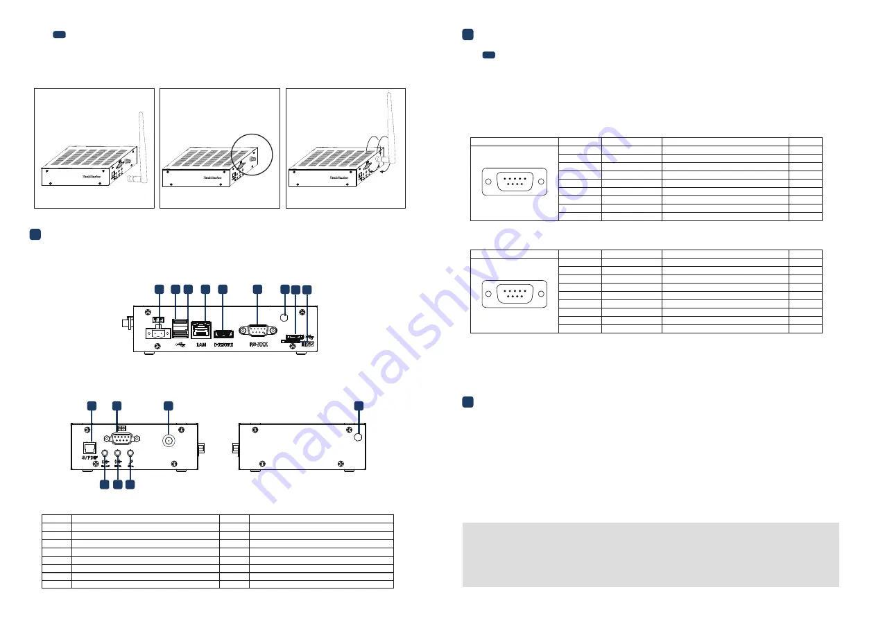
External Connectors
Left side view:
Right side view:
• All Rights Reserved. No part of this document may be photocopied, reproduced, stored in a retrieval system, or transmitted, in any
form or by any means whether, electronic, mechanical, or otherwise without the prior written permission of TechNexion Ltd.
• No warranty of accuracy is given concerning the contents of the information contained in this publication. To the extent permitted
by law no liability (including liability to any person by reason of negligence) will be accepted by TechNexion Ltd., its subsidiaries or
employees for any direct or indirect loss or damage caused by omissions from or inaccuracies in this document.
• TechNexion Ltd. reserves the right to change details in this publication without notice. Please download the most updated version
at: https://www.technexion.com/support/download-center/
Description
No.
No.
Description
1
Power Input connector
USB Host connector
USB Host connector
LAN RJ45 connector
HDMI connector
RS-XXX (Serial Port) connector
Antenna hole
USB OTG connector
MicroSD cardslot
S/PDIF connector
GPIO connector
Antenna connector
3.5mm jack Line out
3.5mm jack Line in
3.5mm jack Mic in
Antenna hole
2
3
4
5
6
7
8
9
10
11
12
13
14
15
16
Phone: +886-2-82273585
Web: www.technexion.com
16F-5, No. 736, Zhongzheng Road,
ZhongHe District, 23511, New Taipei City, Taiwan
© 2001-2019 TechNexion Ltd.
2019-06-25
The unit is preloaded with software that can download and install a selection of OS images over hardwired
network. Simply connect a display to the unit though the HDMI connector and a network through the
Ethernet LAN RJ45 connector and power it up, then follow the steps on the screen to load the software.
Local proxies will interfere with this process. For more information, go to our Knowledge Base at:
https://www.technexion.com/support/knowledge-base/
6
Software Installation
This product is available with two non-galvanic isolated serial ports: a full function RS-232/422/485
(RS-XXX) and a 4-wire RS-232 (IOIO). The RS-XXX port is set as RS-232 during manufacturing. The ports
have the following pinout:
5
Pin Definition
3
4
3.1
Wi-Fi antenna
5.1
Serial Port Connectors (RS-XXX/IOIO)
Please follow the steps below to properly install the Wi-Fi antenna.
Step 1: Prepare development board and Wi-Fi antenna.
Step 2: Locate the round Wi-Fi antenna connector on the development board.
Step 3: Screw the base of the Wi-Fi antenna into the antenna connector.
Top side view:
2 3 4 5
6
7
1
8 9
10
11
12
13 14
16
15
1
2
3
Header on EDM1-FAIRY-IMX6: DB9 (9-pin) standard D-Sub male connector.
Cable receptacle: DB9 (9-pin) standard D-Sub female connector.
RS-XXX:
IOIO:
Signal
Description
5
9
6
1
Port
Pin #
Device
1
NC
SERIAL2_RXD
SERIAL2_TXD
NC
GND
NC
SERIAL2_RTS
SERIAL2_CTS
NC
2
ttymxc0
ttymxc0
ttymxc0
ttymxc0
3
4
5
6
7
8
9
Port#2 Receive data (input)
Port#2 Transmit data (output)
Ground
Port#2 Request-to-send (output)
Port#2 Clear-to-send (input)
Signal
Description
5
9
6
1
Port
Pin #
Device
1
SERIAL1_DCD
SERIAL1_RXD
SERIAL1_TXD
SERIAL1_DTR
GND
SERIAL1_DSR
SERIAL1_RTS
SERIAL1_CTS
SERIAL1_RI
2
ttymxc1
ttymxc1
ttymxc1
ttymxc1
ttymxc1
ttymxc1
ttymxc1
ttymxc1
3
4
5
6
7
8
9
Port#1 Data Carrier Detect (input)
Port#1 Receive data (input)
Port#1 Transmit data (output)
Port#1 Data Terminal Ready (output)
Ground
Port#1 Data Set Ready (input)
Port#1 Request-to-send (output)
Port#1 Clear-to-send (input)
Port#1 Ring Indicator


