


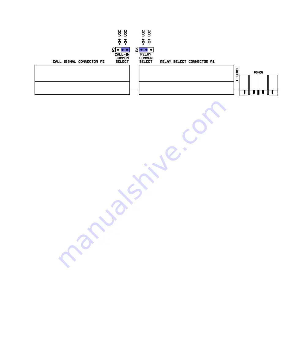
Jumper Options:
The ICR-116 has two sets of Configuration Jumpers to accommodate various PLC Control Options .
Both sides of the Relay Power Supply are connected to the ICR-116. When the Power Supply is
connected properly, the Power Indication should be lighted Green.
CALL COMMON SELECT:
CALL COMMON is connected to all Station Connectors - Pin 4 and Pin 3 of the Power Connector.
The CALL COMMON may be referenced to either Power Supply rail, allowed to float, or referenced to
an external “Common”.
In most Installations, the CALL COMMON is referenced to the Relay Power Supply. For Convenience
the Jumper may be in either Position:
+24 VDC CALL COMMON is connected to the +24 VDC Relay Power Supply Rail
-24 VDC CALL COMMON is connected to the -24 VDC Relay Power Supply Rail
If the CALL COMMON Jumper is removed, the CALL COMMON pin on the POWER Connector floats
and may reference to any source.
RELAY COMMON SELECT:
The Relay SELECT-X lines may be reference to either Rail of the Relay Power Supply
+24 VDC Sinking Drivers, Relay indicators will light Green when a relay is energized
-24 VDC Sourcing Drivers, Relay indicators will light Red when a relay is energized
NOTES:
CALL COMMON is connected to CHASSIS with a 1MEG-Ohm resistor
-24 VDC is connected to CHASSIS with another 1MEG-Ohm resistor
The +24VDC has a 500MA Resettable Fuse for the Relays
The +24VDC has another 500MA Resettable Fuse for the SELECT & CALL Connectors
Содержание ICR-116
Страница 6: ...Schematic Diagram ICR 116B 1 SCHEMATIC DIAGRAM...
Страница 8: ...This Page Has Been Intentionally LeftBlank...


