


Changes to this manual are as shown below. Revised or additional issues of this manual are available from
Tecalemit Garage Equipment Co. Ltd. PLYMOUTH.
Minor changes are indicated by the use of a broad line adjacent to the affected text.
ISSUE STATUS DATE
Issue 1 18/08/2006
Copyright © Tecalemit Garage Equipment Co. Ltd. No part of this publication may be
reproduced, stored or introduced into a retrieval system, or transmitted in any form or by
any means (electronic, mechanical, photocopying, recording or otherwise) without the prior
written permission of Tecalemit Garage Equipment Co. Ltd.
Contents
HEALTH AND SAFETY
3
WARNINGS,
CAUTIONS
AND
NOTES
3
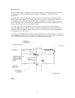
DESCRIPTION
4
INSTALLATION
5
Site
5
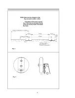
Installing
Rails
5
General
Installation
7
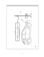
Alignment Mirror
7
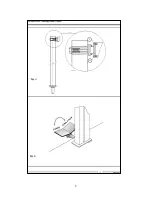
Column Locking Pedal
7
Column Guide Adjusters 8
CALIBRATION
-
SAFETY
PRECAUTIONS
See
Separate
manual
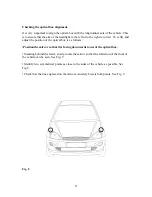
METHOD OF INSPECTION
9
EUROPEAN
TYPE
HEADLAMP
-
CHARACTERISTICS
14
Reason for Rejection
14
BRITISH AMERICAN TYPE (CHECKED ON MAIN BEAM) – CHARACTERISTICS
22
Reason
for
Rejection
22
BRITISH AMERICAN TYPE (CHECKED ON DIPPED BEAM) – CHARACTERISTICS
24
Reason
for
Rejection
24
MAINTENANCE
26
Weekly
26
Six
Monthly
26
MAINTENANCE
-
LUXMETER
26
DISPOSAL
26
SPECIFICATION
27
2


