background image

November, 99

All Rights Reserved

5

B-443 Bar Code Printer
Service Manual

n


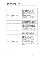
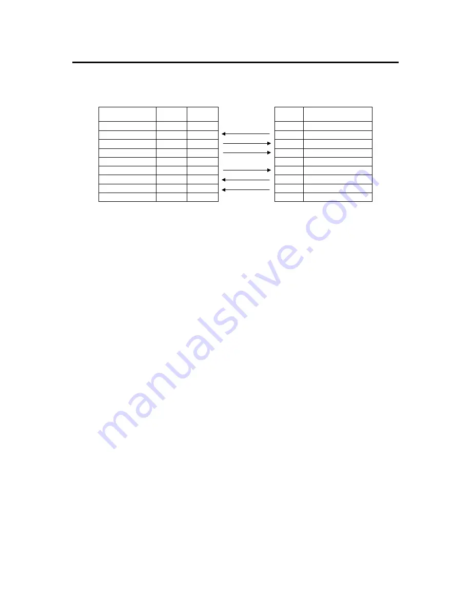
RS-232 Interface Pin Configuration:

Host Function

9 Pin

25 Pin

9 Pin

Printer Function

1

+5V

RxD

2

3

2

TxD

TxD

3

2

3

RxD

DTR

4

20

4

DSR

GND

5

7

5

GND

DSR

6

6

6

RDY

RTS

7

4

7

N/C

CTS

8

5

8

RDY

9

+5V

Содержание B-443

Страница 1: ...TEC Bar Code Printer B 443 Original Oct 1999 Revision Document No EO0 33006 PRINTED IN JAPAN Service Manual...

Страница 2: ...LOCK CIRCUIT 20 3 7 DECODE CIRCUIT 21 3 8 THERMAL HEAD DRIVE PROTECTION AND HISTORY CONTROL CIRCUIT 23 3 9 24V 5V CONVERTER CIRCUIT 24 3 10 STEPPING MOTOR AND DC MOTOR DRIVER PROTECTION CIRCUIT 25 3 1...

Страница 3: ...Printer Service Manual 5 TROUBLE SHOOTING 67 5 1 ERROR MESSAGES 67 5 2 TROUBLE SHOOTING 68 5 3 CALIBRATE THE GAP REGISTER 69 5 4 SELF TEST 69 5 5 RAM CLEAR 69 5 6 DIAGNOSIS OPERATION PROCEDURE 69 5 7...

Страница 4: ...desired label forms with ease 3 B 443 bar code printer can be connected to personal computer or optional LCD keyboard to execute the programs downloaded in the printer s memory The printer is equipped...

Страница 5: ...November 99 All Rights Reserved 2 B 443 Bar Code Printer Service Manual 1 3 Overview 1 3 1 Front View Fig 1 1 Front View of B 443 Front Panel Cover Release Button Top Cover Operation Panel...

Страница 6: ...r 99 All Rights Reserved 3 B 443 Bar Code Printer Service Manual 1 3 2 Rear View Fig 1 2 Rear view of B 443 DC Power Jack RS 232 Interface Centronics Interface Label Entrance External Mount Use Power...

Страница 7: ...ensor n Equipped with Real Time Clock n Comes with self peeling function n Buzzer provided to warn of possible errors n Label stock and thermal transfer ribbon easy to install n Internal label print c...

Страница 8: ...B 443 Bar Code Printer Service Manual n RS 232 Interface Pin Configuration Host Function 9 Pin 25 Pin 9 Pin Printer Function 1 5V RxD 2 3 2 TxD TxD 3 2 3 RxD DTR 4 20 4 DSR GND 5 7 5 GND DSR 6 6 6 RDY...

Страница 9: ...2284mm Label Ticket Width 25mm 103mm Effective Print Width 23mm 101mm No Print Area 1mm 1 6 Available Bar Codes n Code 39 n Code 93 n Code 128 UCC n Code 128 Subsets A B and C n Codabar n Interleaved...

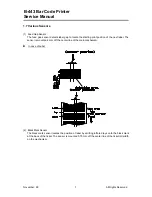
Страница 10: ...arting print position of the next label The sensor is mounted 4 mm off the center line of the main mechanism n In case of Label 2 Black Mark Sensor The black mark sensor locates the position of label...

Страница 11: ...ance There can be only one position for the sensor Once the sensor position is agreed upon it can not be changed afterwards 3 Ribbon End Sensor The sensor detects the end portion of the ribbon The rib...

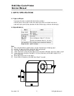
Страница 12: ...r Max 4 3 110mm Max Roll Diameter 1 core External roll diameter Max 8 4 214mm Roll Up Method Print surface wound outside as standard Paper Core ID 25 7 0 3mm Note 1 The width and thickness quoted abov...

Страница 13: ...Min 40mm Max 110mm Ribbon winding width Min 40mm Leading tape Polyester film 335 5mm long End tape Polyester film transparent 250 5mm long Max ribbon OD 67mm Winding method Ink surface to be wound out...

Страница 14: ...er corresponding to the ribbon width 1 This cannot be used when a serial bar code is printed and print density should be lower at 40 degree 2 This cannot be used when a serial bar code is printed at 3...

Страница 15: ...KV Speed 1 5 Density 6 15 Speed 2 0 Density 7 15 Speed 3 0 Density N A 6 SONY TR 4070 Flexcon 22830 SPS 007 Polyester label Static Electricity Max 0 6 KV Speed 1 5 Density 10 15 Speed 2 0 Density 13 1...

Страница 16: ...60 A10 D10 61 A9 D9 62 A8 D8 63 A7 MA7 64 A6 MA6 65 A5 MA5 66 A4 MA4 67 A3 MA3 68 A2 MA2 69 A1 MA1 70 A0 MA0 71 P97 DMAREQ3 72 P96 DMAACK3 73 P94 DMAACK2 75 P92 77 P95 DMAREQ2 74 P93 DMAREQ1 76 P91 D...

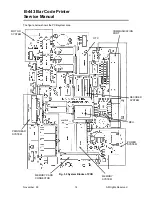
Страница 17: ...4 B 443 Bar Code Printer Service Manual The figure below shows the PCB system area Fig 3 2 System Blocks of PCB MOTOR SYSTEM MEMORY SYSTEM RTC COMMUNICATION PORT DECODER SYSTEM PRINTHEAD SYSTEM POWER...

Страница 18: ...from this pin is L BYTE Bus width selection input Input In memory expansion mode or microprocessor mode this pin determines whether the external data bus is of 8 bit width or 16 bit width The width i...

Страница 19: ...used for 8 bit I O It has basically the same function as port P4 In addition it provides timer A2 timer A3 timer A4 with I O pins and TimeB0 and TimeB1 with input pins P60 P67 I O port P6 I O This po...

Страница 20: ...A14 A15 A16 A17 A18 DO0 DO1 DO2 DO3 DO4 DO5 DO6 DO7 OE DRAMOE ROM1 MA0 MA1 MA2 MA3 MA4 MA5 MA6 MA7 DO0 DO1 DO2 DO3 DO4 DO5 DO6 DO7 LCAS UCAS R W VCC VCC DO 0 7 MA 0 9 A 8 23 A18 1 A16 2 A15 3 A12 4 A7...

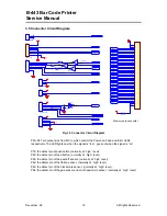
Страница 21: ...A22 A23 E R W OE DO0 DO1 DO2 DO3 DO4 DO5 DO6 DO7 5V 24V 5V 5V 5V 5V 5V 5V P65 CUTTER P53 PH_DETECT P45 P46 P47 P72 P60 P62 P63 P57 DC_MOTOR_A DC_MOTOR_B P64 GAP_EMITTER Fig 3 5 Connector Circuit Diag...

Страница 22: ...ck if the cutter is in right position normally at high level JP8 the connector which connects the external memory module CUTTER the control pin of the CUTTER system DC_MOTOR_A the control pin of the D...

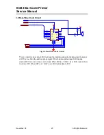
Страница 23: ...7A DO0 DO1 DO2 DO3 DO4 DO5 DO6 DO7 DO 0 7 DO 0 7 5V DS RTC AS R W BZ1 R50 5 6K C66 0 1u RES 5V BUZZER Fig 3 6 Real Time Clock Circuit This is a real time clock circuit MCU will read the date time and...

Страница 24: ...0 7 ALE E RESET CENTRONIC ROM2 ROM3 ROM12 ROM11 MA0 Fig 3 7 Decode Circuit This is the decode circuit which calculates memory map U3 is used to latch addresses from DO0 to DO7 The main function of U8...

Страница 25: ...M4 MEMORY CARD 6FFFFFH 600000H 5FFFFFH 500000H FLASH ROM EXTERNAL ROM3 MEMORY CARD RTC ADDRESS PORT RTC DATA PORT CENTRONIC PORT PARALLEL COMMUNICATION 400001H 400000H 380000H 2FFFFFH 200000H FLASH RO...

Страница 26: ...LAT 6 CLK 7 VDD 8 STB1 9 STB2 10 STB3 11 PGND 12 PGND 13 PGND 14 PGND 15 JP91A ROHM_PD1 PGND 1 PGND 2 PGND 3 PGND 4 LGND 5 TM 6 TM 7 STB4 8 STB5 9 STB6 10 DI 11 VH 12 VH 13 VH 14 VH 15 JP92B ROHM_PD1...

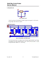
Страница 27: ...2 1 L23 BEAT B1 DC JACK 24V C10 0 1u C6 1500pF C9 1000u 35V SW1 SW SPDT R56 470 2W L14 CHOKE D3 SR505 C82 0 01u 0 01u L26 1 2 3 4 L4 COMM_CHOKE Fig 3 10 24V 5V Converter Circuit Figure 3 10 is the DC...

Страница 28: ...A4 8 2A1 11 2A2 13 2A3 15 2A4 17 1Y1 18 1Y2 16 1Y3 14 1Y4 12 2Y1 9 2Y2 7 2Y3 5 2Y4 3 1G 1 2G 19 U6 74LS244 C30 10u TANT 1 2 3 4 5 6 7 JP3 CUTTER PEEL DIGITAL_GND PEEL VCC DIGITAL GND MOTOR_GND 1 2 3 4...

Страница 29: ...100 R31 100 R33 100 R34 100 R35 100 R36 100 PE ERROR SELECT VCC DO 0 7 DO 0 7 DO0 DO1 DO2 DO3 DO4 DO5 DO6 DO7 CENTRONIC INT C71 0 1u CGND CGND CGND CGND DIGITAL GND DIGITAL GND 5 6 U11C 74LS14 8 9 U11...

Страница 30: ...9 GND 8 U20B 2003 3 14 9 GND 8 U20C 2003 4 13 9 GND 8 U20D 2003 C30 10u TANT 1 2 3 4 5 6 7 JP3 CUTTER PEEL PEEL 5V D16 DSP D17 DSP CUTTER Fig 3 13 Cutter Drive Circuit This is the cutter drive circui...

Страница 31: ...printer power 2 Remove the power cord and RS 232 and or parallel port cable 3 Open the top cover of the printer 4 Remove the printer front panel Fig 3 14 Remove the front cover in the direction of th...

Страница 32: ...move the peel off sensor connector Fig 3 16 Cable tie and peel off sensor connector 7 Remove the screws on the lower left and lower right corners of main mechanism Fig 3 17 Remove the screws in the lo...

Страница 33: ...t 9 Move the mechanism about 5 mm in the label feed direction 10 Take out the internal label roll mount and remove the connector Fig 3 19 Take out the internal label roll mount and remove the connecto...

Страница 34: ...f sensor connector JP4 Black mark sensor connector JP5 Gap ribbon transmit sensor connector JP6 DC motor and encoder connector JP7 TPH head up switch connector JP8 Memory cartridge connector JP9 TPH c...

Страница 35: ...remove the peel off sensor connector 7 Remove the screw on the PCB of peel off and cutter connector 8 Remove the screws in the lower left lower right corners of main mechanism 9 Remove all four screw...

Страница 36: ...cutter does not work please check that the software or program has been switched to the cutter mode If the cutter still does not function please check the cutter driver IC make sure it is firmly inser...

Страница 37: ...e the cable tie and remove the peel off sensor connector Cf Fig 3 16 6 Remove the peel off sensor connector Cf Fig 3 17 7 Plug in the cutter connector 8 Insert the right and left side flange of cutter...

Страница 38: ...the RS 232 cable and power cord 3 Open the top cover 4 Remove the ribbon and label roll 5 Open the print carriage 6 Remove the screw at the top front center of the mechanism as shown Fig 4 2 The Prin...

Страница 39: ...Note The key of connector must be positioned upward Do not touch the elements of the print head Do not disassemble the print head 8 Tidy up the cable so that it does not protrude or interfere with th...

Страница 40: ...s in the lower left lower right corners of the main mechanism 9 Remove all four screws of the internal label roll mount Cf Fig 3 18 10 Move the mechanism in the label feed direction about 5 mm 11 Take...

Страница 41: ...printer to thermal transfer mode The multi meter is used to measure the voltage of Pin2 5V If the voltage changes continuously from 0 to 5 volts DC the encoder is in condition Otherwise please follow...

Страница 42: ...the best printing quality Follow the steps below to replace the felt fabric 1 Follow the instructions in Section 4 3 to remove DC motor and DC motor fixture 2 Remove the E ring and washer on ribbon s...

Страница 43: ...November 99 All Rights Reserved 40 B 443 Bar Code Printer Service Manual 6 Reassemble the removed parts in the reverse order of removal Fig 4 8 Front View of the Ribbon Supply Spindle...

Страница 44: ...onnector 8 Remove the screws in the lower left lower right corners of the main mechanism Cf Fig 3 17 9 Remove all four screws of the internal label roll mount Cf Fig 3 18 10 Move the mechanism in the...

Страница 45: ...printer 4 Remove the printer front panel Cf Fig 3 14 5 Remove the two screws and the metal cover Cf Fig 3 15 6 Release the cable tie and remove the peel off sensor connector Cf Fig 3 16 7 Remove the...

Страница 46: ...of peel off and cutter connector 8 Remove the screws in the lower left lower right corners of the main mechanism Cf Fig 3 17 9 Remove all four screws of the internal label roll mount Cf Fig 3 18 10 Mo...

Страница 47: ...ferent in shape The right side spring has a straight end whereas the left side spring has an end that is curved 90 degrees 16 The main mechanism is divided into upper mechanism and lower mechanism 17...

Страница 48: ...the steps in Section 4 6 to separate the upper mechanism from the lower mechanism 2 The ribbon sensor transmitter is located in the center of the lower mechanism Fig 4 14 Ribbon Sensor Transmitter 3 R...

Страница 49: ...Fig 3 17 9 Remove all four screws of the internal label roll mount Cf Fig 3 18 10 Move the mechanism in the label feed direction about 5 mm 11 Take out the internal label roll mount and remove the con...

Страница 50: ...carriage release lever arm and E ring 19 Remove the teflon tube and metal rod Fig 4 18 20 Remove the E ring the left side and right side platen bushes Fig 4 19 21 Remove the stripper plate Printer Ca...

Страница 51: ...g 4 18 Teflon tube and metal rod Fig 4 19 Remove E ring and platen bush 22 Move the platen a bit to the right of the mechanism take out the platen 23 Replace the platen and reassemble the removed part...

Страница 52: ...Bar Code Printer Service Manual 4 11 Head Up Sensor Replacement 1 Remove the four screws with an electric screwdriver 1 Take out the ribbon mechanism place it on the right side 2 Remove the screws on...

Страница 53: ...All Rights Reserved 50 B 443 Bar Code Printer Service Manual 2 Lay a piece of cloth under the printhead 2 Remove the 2 printhead spring blade fixing screws 3 Pry off the left and right bushes with a...

Страница 54: ...rved 51 B 443 Bar Code Printer Service Manual 2 Pry off the torsion springs on either side 4 Press the torsion spring lift main mechanism cover with fingers 4 Press the cover with the thumb pull up an...

Страница 55: ...d 52 B 443 Bar Code Printer Service Manual 5 Place printhead on the cloth with the cover facing up 5 Remove the screw and touch spring with a cross screwdriver 6 Replace and fix the 1 7 3 tap screw an...

Страница 56: ...ts Reserved 53 B 443 Bar Code Printer Service Manual 7 Loosen the 3 M3 6 screws on the printhead bracket 8 Take out the printhead bracket remove the spring blade 8 Replace the printhead bracket put ba...

Страница 57: ...ervice Manual 9 Fasten the M3 6 ground wire screw with 2 washers then lock the M3 6 TPH screw 10 Press on one end of the torsion spring with both thumbs fit in the main mechanism upper cover with both...

Страница 58: ...down with both thumbs fit in the bushes with both index fingers 11 Align printhead bracket spring blade with the tenons ofupper cover fit the two together 11 Fix the two in place with 2 2 6 12 screws...

Страница 59: ...November 99 All Rights Reserved 56 B 443 Bar Code Printer Service Manual 12 Fix in place with 2 3 15 screws 12 Place ribbon mechanism on main mechanism fix it in place with 4 3 8 screws...

Страница 60: ...80016 00 37 1402005 31 98 0130055 00 98 0130069 00 98 0180060 00 52 0300021 21 32 0130015 00 30 0130041 00 80 ULN2003 00 80 PBL3717 00 82 029C040 00 Screw 3x8 Memory Module Cover Push Botton Box Ass y...

Страница 61: ...November 99 All Rights Reserved 58 B 443 Bar Code Printer Service Manual...

Страница 62: ...0130019 10 98 0180009 10 37 1403005 32 37 1403008 34 37 1203510 31 30 0130014 10 98 0180011 10 37 1502604 34 37 1201705 24 98 0180015 10 36 0180002 00 Ribbon Spindle Ass y Ribbon Mechanism Ass y Screw...

Страница 63: ...November 99 All Rights Reserved 60 B 443 Bar Code Printer Service Manual...

Страница 64: ...1 3 12 98 0180069 00 37 1403008 34 37 1202612 22 37 1503006 34 37 1403015 32 37 1403508 52 98 0180012 00 37 1201705 24 72 0050003 00 64 0010011 00 32 0130041 20 37 1201703 32 Mechanism Upper Cover Ass...

Страница 65: ...November 99 All Rights Reserved 62 B 443 Bar Code Printer Service Manual 11 12...

Страница 66: ...4 8 4 9 4 10 4 11 98 0180070 00 98 0180013 00 65 0010005 00 37 1403008 34 37 1403006 74 36 0130002 00 30 0130053 10 98 0180014 00 37 1201705 24 36 0130001 40 37 1503004 14 Mechanism Lower Cover Ass y...

Страница 67: ...November 99 All Rights Reserved 64 B 443 Bar Code Printer Service Manual...
Страница 68: ...Printer Service Manual Accessories Ref No Part No Description Remarks List Price 5 1 5 2 5 3 5 5 72 0010001 00 98 0130050 00 62 0130003 01 36 0130038 00 Parallel Port Cable External Label Roll Mount A...

Страница 69: ...November 99 All Rights Reserved 66 B 443 Bar Code Printer Service Manual...

Страница 70: ...exceeds that of the label Download Error The format of the downloaded file is incorrect There is not enough memory to store the file Stack Overflow Program contains too complex mathematical expressio...

Страница 71: ...lluminate Check the connection of serial port cable 5 On line indicator light does not to illuminate Check the DIP switch setting and reset the printer Check that power cord is properly connected 6 Er...

Страница 72: ...2 Calibrate the label length 3 Print internal settings 4 Initiate self test 5 Enter dump mode 5 5 Ram Clear Press the PAUSE and FEED button simultaneously for more than 3 seconds The printer will clea...

Страница 73: ...he measured voltage should be 5 Vdc 2 When gap of the gear box is not detected by the DC motor encoder sensor the measured voltage should be 0 Vdc The DC motor encoder sensor is normal if the checking...

Страница 74: ...the measured voltage should be 0 Vdc The black line sensor is normal if the checking complies with the two cases above Or else the black line sensor is out of order E Checking Peel Off Sensor Switch t...

Страница 75: ...formance The greater the usage of the printer the more frequent the cleaning 1 Turn the power off 2 Open the printer cover 3 Open the printer carriage by pulling up the release lever to the left of th...

Страница 76: ...ll warnings and cautions contained in this manual and written inside or outside of the printer should be read and understood before handling or maintaining the equipment Never modify the machine Excep...

Отзывы: