background image

53

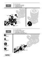
G-7

EN


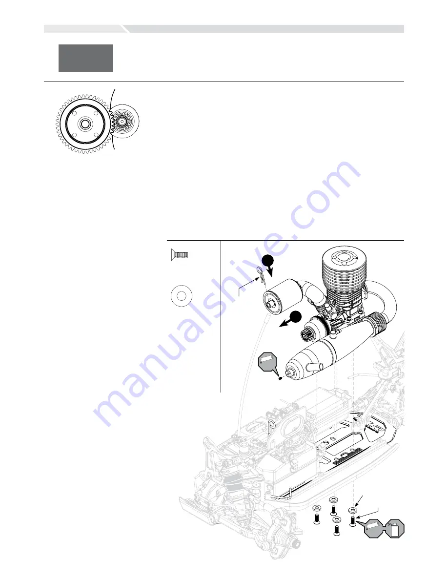
Engine Installation

DE

 Motoreinbau

FR 

Installation du moteur

IT 

Installazione del motore

ES


Instalación del motor

TLR8202

LOSA6351

LOSA6262

TLR-LOK

TLR-LOK

1

2

EN

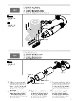
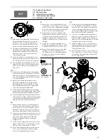
1. 

Adjust the gear mesh between the Clutch Bell and the 
Spur gear by sliding the engine mounts in the slots of 
the chassis. In order to function properly, the Gears 
should be as close as possilbe, but still have a small 
amount of backlash (space between the Gear teeth). 

2. 

Place a piece of paper between the Clutch Bell gear 
and Spur gear, then slide the engine sideways until 
the paper is pinched between the gears. Tighten the 
engine mount screws. This will give a small amount  
of space between the gears.

3. 

You should be able to rock one gear back and forth 
slightly while holding the other gear steady. Be sure to 
check the gear mesh all the way around the spur gear.

4. 

Once the engine alignment and gear mesh are correct, 
tighten all of the screws. Re-check the gear mesh after 
all the screws are tight to ensure the engine mounts 
did not move.

DE

1. 

Justieren Sie das Zahnflankenspiel zwischen Kupplungs-
glocke und Zahnrad durch verschieben der Motorhalter 
in den Chassisschlitzen. Für eine  einwandfreie Funktion 
sollten die Zahnräder nah zusammenstehen, aber immer 
noch etwas Spiel haben.

2. 

Legen Sie eine schmalen Papierstreifen zwischen  
dem Ritzel der Kupplungsglocke und dem Zahnrad  
und schieben den Motor an das Zahnrad ran. Ziehen  
Sie die Befestigungsschrauben an. Der Papierstreifen  
sorgt für das notwendige Zahnflankenspiel. 

3. 

Es sollte möglich sein das Zahnrad etwas zu bewegen 
während Sie das Ritzel festhalten. Prüfen Sie das Zahnflan-
kenspiel bitte auf dem ganzen Umfang des Zahnrades.

4. 

Ist das Zahnflankenspiel richtig eingestellt und der Motor 
korrekt ausgerichtet ziehen Sie die Befestigungsschrauben 
an. Prüfen Sie das Zahnflankenspiel danach erneut und 
prüfen dass der Motor sich dabei nicht bewegt.

FR

1. 

Réglez l’entre-dents entre la cloche d’embrayage et la 
couronne en faisant glisser le support moteur dans les 
rainures du châssis. Pour un fonctionnement correct les 
engrenages doivent être les plus poches possible, mais 
en laissant un léger jeu (jeu fonctionnel entre les dents).

2. 

Glissez un morceau de papier entre les dents de la cloche  
d’embrayage et de la couronne. Faites glissez le moteur 
jusqu’au pincement du papier entre les dents afin 
d’obtenir le bon réglage. Serrez les vis de fixation  
du support moteur. 

3. 

Vous devez pouvoir légèrement faire pivoter la couronne 
quand vous maintenez la cloche d’embrayage. Contrôlez 
le jeu sur toute la circonférence de la couronne.

4. 

Une fois que le réglage est terminé, resserrez toutes les 
vis. Re-contrôlez le jeu afin de vérifier que le support 
moteur ne s’est pas déplacé durant le serrage.

IT

1. 

Regolare il gioco tra la campana della frizione e la 
corona facendo scorrere il supporto motore nelle asole 
sul telaio. Per funzionare correttamente gli ingranaggi 
devono stare il più vicino possibile, conservando però 
un piccolo gioco tra i denti degli ingranaggi.

2. 

Mettere un pezzo di carta tra l’ingranaggio della 
campana della frizione e quello della corona, poi far 
scorrere il motore fino a pizzicare la carta tra i due 
ingranaggi. Stringere le viti di fissaggio del motore. 
Togliendo la carta resterà un piccolo spazio tra i due 
ingranaggi.

3. 

Tenendo fermo uno dei due ingranaggi, l’altro si 
dovrebbe muovere leggermente in avanti  e indietro. 
Accertarsi di verificare il gioco intorno alla corona. 

4. 

Quando l’allineamento del motore e il gioco degli 
ingranaggi sono a posto, stringere tutte le viti.  
Controllare di nuovo il gioco degli ingranaggi dopo 
aver stretto le viti, per accertarsi che il supporto  
motore non si sia mosso.

ES

1. 

Realizar el ajuste entre la campana del embrague y 
la corona deslizando las bancadas del motor en las 
ranuras del chasis. Para conseguir un funcionamiento 
correcto, los engranajes deben estar tan cerca como 
sea posible, pero deberían tener una pequeña holgura 
(espacio entre los dientes de los engranajes).

2. 

Colocar un trozo de papel entre la campana del em-
brague y la corona, a continuación, deslizar el motor 
hasta que el papel se pellizque entre los engranajes. 
Apretar los tornillos de la bancada del motor. Esto dará 
una pequeña holgura entre los engranajes.

3. 

Debería ser capaz de oscilar la corona hacia atrás y 
adelante ligeramente mientras mantiene la campana 
quieta. Asegurarse de revisar el ajuste en toda la 
circunferencia de la corona.

4. 

Una vez la alineación del motor y la corona sean cor-
rectos, apretar todos los tornillos. Volver a comprobar 
la holgura para asegurarse de que las bancadas del 
motor no se han movido.

lOSa6262 x 4

8-32 x 1/2”

lOSa6351 x 4

#8 countersink

Содержание 8IGHT 3.0

Страница 1: ......

Страница 2: ...erious injury Components Engines and some electronic components can become hot while in use Do not touch parts until cool Should any compatibility questions exist please refer to the product instructi...

Страница 3: ...sche Komponenten k nnen w hrend des Betriebs hei werden Fassen Sie diese Teile nicht an bevor sie abgek hlt sind Verwenden Sie diese Teile nur mit geeigenten Komponenten Sollten Sie Fragen zur Kompati...

Страница 4: ...s pendant l utilisation Ne touchez pas les pi ces avant qu elles aient refroidi N utilisez qu avec des com posants compatibles Pour toute question de compatibilit consultez les instructions concernant...

Страница 5: ...Alcuni componenti elettronici possono diventare caldi durante il loro uso Non toccarli finch non si raffreddano Usare solo componenti compatibili Se ci sono delle domande in relazione alla compati bil...

Страница 6: ...se pueden calentar con el uso No toque estas partes hasta que se enfr en Utilice s lo componentes compatibles En caso de tener alguna duda de compatibilidad acuda a las instrucciones del producto las...

Страница 7: ...ale implication dans le monde de la RC Chaque course que nous avons remport e chaque v hicule que nous avons con u toutes nos exp riences men es jusqu pr sent nous ont aid cr er le 8IGHT 3 0 Cette pla...

Страница 8: ...leinteile links neben jedem Schritt Die Silhouette der einzelnen Teile ist 1 1 Originalgr e Um zu berpr fen ob Sie das richtige Teil haben halten Sie es gegen die Silhouette FR Organisation du Kit Man...

Страница 9: ...ial atenci n CUT Cut Trim Schneiden Abgleichen Couper bavurer Tagliare regolare Corte lime Ensure Free Movement Leichtg ngigkeit sicherstellen V rifier la libert de mouvement Assicurare un movimento l...

Страница 10: ...all ends LOSA6045 x 1 5 40 x 7 8 LOSA6256 x 1 4 40 x 1 2 Tools Required Erforderliche Werkzeuge Outils n ces saires Utensili necessari Herramientas requeridas English Deutsch Fran ais Italiano Espa ol...

Страница 11: ...saver nut all the way down then back off 5 1 2 turns DE Ziehen Sie die Mutter des Servo Savers fest an und drehen Sie sie dann 5 Umdrehungen zur ck FR Serrez compl tement la bague du sauve servo puis...

Страница 12: ...Placa superior A 5 EN Completed Steering Assembly DE Vollst ndige Baugruppe Lenkung FR Ensemble de direction termin IT Assemblaggio completo dello sterzo ES Montaje completo de la direcci n LOSA6271...

Страница 13: ...es FR Assemblage du corps de diff rentiel IT Assemblaggio alloggiamento diff ES Montaje caja de diferencial LOSA3553 LOSA6948 LOSA3509 LOSA3505 LOSA3501 LOSA3502 1 2 3 4 LOSA3518 LOSA3553 LOSA6948 LOS...

Страница 14: ...lir d huile 5000 wt jusqu au dessus des satellites IT Riempire con olio 5000 wt fino sopra l ingranaggio planetario ES Llene con hidr ulico de 5000wt hasta cubrir los en granajes OIL EN Tighten the di...

Страница 15: ...el appliquez un fin bourrelet de graisse sur toute la longueur de la jonction IT Per evitare che le polveri sottili entrino nella scatola ingranaggi mettere un leggero strato di grasso lungo il bordo...

Страница 16: ...245000 TLR244003 LOSA6251 TLR244000 TLR244007 1 2 3 4 5 5 LOSA6266 LOSA6263 TLR244001 LOSA1701 Front Kick Up Angle Adjustment Outer Front Brace Inner Front Brace Total Kick Up Insert Position Insert N...

Страница 17: ...EGOLAZIONE ANGOLO ANTERIORE Supporto esterno anter Supporto interno anter Angolo totale Posizione inserim Numero inserim Posizione inserim Numero inserim superiore 1 inferiore 1 2 superiore 0 5 inferi...

Страница 18: ...dingt die zusammenge baute Spurstange mit der Nut neben dem Mittelst ck zur leich teren sp teren Justierung auf der linken Seite des Fahrers auf dem Auto anbringen 95 5mm LOSA6049 TLR244002 LOSA6278 L...

Страница 19: ...lter FR Montage des entretoises d amortisseurs IT Assemblaggio supporto ammortizzatore ES Montaje del soporte del amortiguador B 9B LOSA6302 LOSA6280 LOSA6311 TLR243000 L R L R L LOSA6311 x 1 8 32 x 1...

Страница 20: ...ciliter les futurs r glages IT Bisogna installare sull auto il tirante montato con la scanala tura vicino alla sezione quadrata centrale rivolta verso sinistra per poterlo regolare facilmente in segui...

Страница 21: ...ontaje del grupo delantero EN Steering Rod Assembly DE Zusammenbau Lenkstange FR Installation des biellettes de direction IT Montaggio tirante sterzo ES Montaje del tirante de direcci n B 11A B 11B LO...

Страница 22: ...22 EN Completed Front End Assembly DE Fertigstellung des Vorderwagens FR Assemblage du train avant termin IT Assemblaggio parte anteriore completato ES Montaje completo secci n frontal B 12...

Страница 23: ...uses FR Assemblage du corps de diff rentiel IT Assemblaggio alloggiamento diff ES Montaje caja de diferencial LOSA6948 LOSA3518 LOSA3505 LOSA3501 LOSA3502 LOSA3556 LOSA3554 1 2 3 4 LOSA3518 3 LOSA3505...

Страница 24: ...huile 7000 wt jusqu au dessus des satellites IT Riempire con olio 7000 wt fin sopra al l ingranaggio planetario ES Llene con hidr ulico de 7000wt hasta cubrir los en granajes OIL EN Tighten the diff...

Страница 25: ...bly DE Zusammenbau des Gest nges FR Assemblage des tringleries IT Assemblaggio barrette comandi ES Montaje del varillaje TLR4406 LOSA6109 0 5mm 7mm TLR LOK LOSA4420 LOSA6297 LOSA3544 LOSA3544 LOSA9168...

Страница 26: ...cona al tama o de la imagen LOSA6227 LOSA9168 LOSA9168 LOSA9135 LOSA9168 TLR LOK EN Assemble both Front and Rear Brake Lever Collars 2 80mm 11 from the end of the Brake Rod DE Justieren Sie die Stellr...

Страница 27: ...IT Assemblaggio pinze freno ES Montaje de frenos TLR242005 TLR242005 7 8mm EN Air Filter Guard DE Luftfilterschutz FR Protection de filtre air IT Protezione filtro aria ES Protector filtro de aire C...

Страница 28: ...IT Assemblaggio differenziale centrale Disco freno ES Montaje de diferencial central Discos frenos C 10A EN Front Center Dogbone Assembly DE Montage Zentralwelle FR Installation du cardan central avan...

Страница 29: ...lot of the center outdrive while installing the Center Diff assembly DE Hinweis Bitte stellen Sie sicher dass die Achswelle in die Zentralknochenaufnahme eingesetzt ist w hrend Sie die Zentraldifferen...

Страница 30: ...es FR Assemblage du corps de diff rentiel IT Assemblaggio scatola differenziale ES Montaje caja de diferencial LOSA3553 LOSA3502 LOSA3505 LOSA3510 LOSA6948 LOSA3518 1 2 3 4 LOSA3501 1 2 3 4 LOSA3502 L...

Страница 31: ...riebe f llen FR Remplir d huile 3000 wt jusqu au dessus des satellites IT Riempire con olio 3000 wt appena l ingranaggio planetario ES Llene con hidr ulico de 3000wt hasta cubrir los en granajes OIL E...

Страница 32: ...o gioco degli ingranaggi con il vostro nuovo veicolo ES El kit del 8IGHT 3 0 viene con 2 arande las de 0 25mm en el lado izquierdo del casquillo del rodamiento y 1 arandela de 0 25mm as como 1 arandel...

Страница 33: ...los trapecios de la suspensi n trasera L R L R L LOSA6296 x 1 F 8 32 x 1 8 LOSA3518 x 1 2 5 x 12 80mm LOSA3518 x 1 3 x 17mm LOSA6945 x 1 8 x 14 x 4mm LOSA6953 x 1 1 2 x 3 4 Rear Toe In Adjustment Ins...

Страница 34: ...cabrage total Haut 1 3 Haut 0 5 2 5 Milieu 0 2 Bas 0 5 1 5 Bas 1 1 REGOLAZIONE CONVERGENZA POSTERIORE Posizione inserim Numero inserim Convergenza tot Interno 1 2 Interno 0 5 2 5 Centrale 0 3 Esterno...

Страница 35: ...Installez la rotule de barre stabilisa trice sur la tige de barre stabilisa trice jusqu ce qu elle soit fleur de la rotule figure ci dessus IT Inserire le sfere nella barra oscil lante finch il filo...

Страница 36: ...de la torreta de amortiguador trasera D 10A EN Tie Rod Installation DE Einbau der Spurstange FR Installation des biellettes de carrossage IT Installazione tirante ES Montaje tirante LOSA6280 99mm LOS...

Страница 37: ...al arri re IT Assemblaggio giunto cardanico ES Montaje del palier central trasero EN Tie Rod Installation DE Einbau der Spurstange FR Installation des biellettes de carrossage IT Installazione tirante...

Страница 38: ...t ist wenn Sie die Zentraldifferenzial Baugruppe einbauen FR Contr lez que l extr mit du cardan est correctement ins r e dans la noix de sortie du diff rentiel central quand vous installez le train ar...

Страница 39: ...39 D 13 EN Completed Rear Assembly DE Abgeschlossener Heckzusammenbau FR Train arri re install IT Assemblaggio posteriore completato ES Montaje completo secci n trasera...

Страница 40: ...t 25wt l bis zur Oberkante auf 7 Bewegen Sie den Kolben 8 Mal rauf und runter Damit l sen Sie Luftblasen die sich am Kolben festgesetzt haben Stellen Sie den gef llten Sto d mpfer aufrecht hin 8 Sind...

Страница 41: ...ring di regolazione nel dado prima di installare il dado sul corpo dell ammortizzatore 1 Limpiar el tornillo 2 56x1 4 y aplicar fijatornillos TLR LOK en la rosca 2 Colocar la arandela grande en cada...

Страница 42: ...ortiguadores delanteros L R L R L LOSA6281 LOSA6350 LOSA6302 LOSA5435 EN Use LOSA6284 on the right suspension arm Use LOSA6281 on the left suspension arm DE Verwenden Sie LOSA6284 auf der rechten Aufh...

Страница 43: ...284 on the left suspension arm Use LOSA6281 on the right suspension arm DE Verwenden Sie LOSA6281 auf der rechten Aufh ngung und LOSA6284 auf der linken Aufh ngung FR Use Utilisez la vis LOSA6284 sur...

Страница 44: ...pporto servo ES Montaje del soporte del servo EN Chassis Guard Installation DE Einbau des Chassis Schutzes FR Installation des bavettes de protection IT Installazione protezione telaio ES Montaje de l...

Страница 45: ...tion DE Schaltereinbau FR Installation de l interrupteur IT Installazione interruttore ES Instalaci n del interruptor LOSA6206 LOSA6350 TLR4401 LOSA6206 LOSA6350 LOSA6210 TLR4410 LOSA4419 TLR4404 TLR4...

Страница 46: ...cevitore ES Instalaci n de la bater a del receptor F 5 LOSA4003 EN Receiver Installation DE Empf ngereinbau FR Installation du r cepteur IT Installazione ricevitore ES Instalaci n del receptor LOSA400...

Страница 47: ...ES Montaje de la bandeja de radio F 8 EN Throttle Horn Installation DE Zusammenbau Gasgest nge FR Installation du palonnier de gaz IT Installazione squadretta servo motore ES Montaje del reenvio del...

Страница 48: ...ecting the servos to the radio system and setting the trim to center DE Bitte stellen Sie sicher dass das Servo mit der Fernsteuer ung zentriert ist bevor Sie das Servohorn aufsetzten FR Contr lez que...

Страница 49: ...49 F 11 EN Completed Radio Tray Installation DE Vollst ndige Montage Radioplatte FR Platine radio install e IT Installazione completa supporto radio ES Montaje completo de la bandeja de radio...

Страница 50: ...7 LOSA9105 LOSA9114 LOSA9108 LOSA9113 LOSA9114 G 2 EN Clutch Bell Assembly DE Zusamenbau Kupplungsglocke FR Assemblage de l embrayage IT Assemblaggio campana frizione ES Montaje de la campana de embra...

Страница 51: ...Papiertuch jegliches bersch ssiges Filter l heraus Das dient der Verbesserung der Motorleistung FR Pressez la mousse l aide d un chiffon propre ou d un mouchoir en papier pour extraire l exc dent d h...

Страница 52: ...ponents DE K rzen Sie den D mpferhalter in kleinen Schritten wie ben tigt Stellen Sie dabei sicher dass der Draht keine anderen Komponent en Lenkung etc behindert FR R glez en proc dant par petits inc...

Страница 53: ...cloche d embrayage et de la couronne Faites glissez le moteur jusqu au pincement du papier entre les dents afin d obtenir le bon r glage Serrez les vis de fixation du support moteur 3 Vous devez pouvo...

Страница 54: ...mpleted Engine Assembly DE Kraftstoffleitung vollst ndige Motorbaugruppe FR Moteur et durites install s IT Assemblaggio completo motore tubetto carburante ES Tubo de combustible Montaje de motor compl...

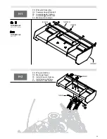
Страница 55: ...ssemblaggio Wickerbill ES Montaje de la solapa H 2 EN Wing Installation DE Montage Fl gel FR Installation de l aileron IT Installazione alettone ES Instalaci n del aler n TLR240003 LOSA6306 TLR240001...

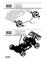
Страница 56: ...des roues IT Installazione ruote ES Montaje de las llantas H 3 H 4 EN Completed Chassis Assembly DE Vollst ndige Chassisbaugruppe FR Assemblage termin IT Assemblaggio completo telaio ES Montaje de cha...

Страница 57: ...e place of purchase Law These terms are governed by Illinois law without regard to conflict of law principals This warranty gives you specific legal rights and you may also have other rights which var...

Страница 58: ...on Hobby Limited Units 1 4 Ployters Rd Staple Tye Harlow Essex CM18 7NS United Kingdom 44 0 1279 641 097 sales horizonhobby co uk Germany Horizon Technischer Service Christian Junge Stra e 1 25337 Elm...

Страница 59: ...hrleistung erhoben werden Horizon wird dar ber hinaus keine Anspr che aus einem Garantiefall akzeptieren die ber den individuellen Wert des Produktes hinaus gehen Horizon hat keinen Einfluss auf den...

Страница 60: ...hange dans le cadre de cette garantie La garantie s applique uniquement aux produits achet s chez un revendeur Horizon agr Les ventes faites des tiers ne sont pas couvertes par cette garantie Les reve...

Страница 61: ...ssible d viter une manipulation erron e et des accidents entra nant des blessures et des d g ts Questions assistance et r parations Votre revendeur sp cialis local et le point de vente ne peuvent effe...

Страница 62: ...essere approvata per iscritto dalla Horizon Limiti di danno Horizon non si riterr responsabile per danni speciali diretti indiretti o consequenziali perdita di profitto o di produzione perdita commerc...

Страница 63: ...rn Germania 49 0 4121 2655 100 service horizonhobby de Informazioni di Servizio clienti Stato in cui il prodotto stato acquistato Horizon Hobby Indirizzo Telefono Indirizzo e mail Germania Horizon Hob...

Страница 64: ...icional Env e el paquete a trav s de una compa a que proporcione un seguimiento y un seguro en caso de p rdida o da o ya que Horizon no se responsabiliza de la mercanc a hasta que esta llega y se acep...

Страница 65: ...Atenci n al Cliente Pa s de compra Horizon Hobby Direcci n Tel fono Direcci n de correo Estados Unidos de America Horizon Service Center Electr nica y motores 4105 Fieldstone Rd Champaign Illinois 618...

Страница 66: ...ogos are property of their respective owners ENGINEERED IN CALIFORNIA TLR04000 800 0472 Horizon Hobby Inc 4105 Fieldstone Road Champaign IL 61822 USA Horizon Hobby Limited Units 1 4 Ployters Rd Staple...

Отзывы: