Copyright © TeacherGeek 2007
Final Wiring
Page
™
E
F
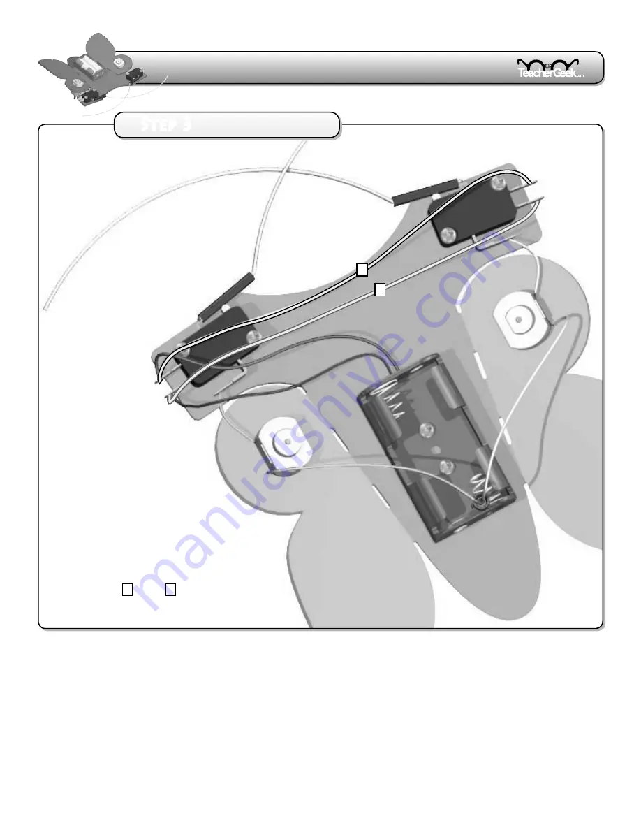
5.
Cut two 7”
(18cm)
wires
(any color).
6.
Strip the wire ends.
7.
Attach the wires as shown
with E and F .
It’s time to solder. See page 8 for instructions.
Step
Страница 1: ... 2 Process 3 Where are we 1 Body Build The mechanical part of the bug is constructed 2 Electronics Lab Bug Experiments teach the fundementals of electronics 3 Final Wiring Permanent wires are soldered on to bring the Bug to life You are here Catch The Bug ...
Страница 2: ...inished Bug without wires Tips and Tricks Hold off on soldering until all the wires have been put on your bug Make sure batteries are removed while wiring Hook wires through terminal holes then pinch smoosh hooked wire to secure Bend out switch terminals to provide more room for wiring Strip 25 6mm of insulation from the ends of wires before connecting them Twist together the stranded ends of wire...
Страница 3: ...r at one end 4 Place the twisted end of the wires into a spade connector 5 Attach the harness to the rear motor terminals M Crimp the spade connector here Wires should extend to here Finished Harness The Spade connector is the Bug s On Off Switch Place it into the rear spring on the battery holder to turn the Bug on The Harness The On Off Switch ...
Страница 4: ...ording to your final Bug wiring Show the your teacher Teacher Signature a go forward when turned on b reverse the motor directly behind the switch that is pushed c not short circuit Use alligator clip leads to experiment creating the final Bug wiring When you figure it out complete the schematic below and show your teacher Permanent wires can be placed onto your Bug and soldered once you receive y...
Страница 5: ...e your final Bug wiring 1 Use the schematic to place the permanent wires on your Bug but don t solder them 2 Show your teacher your Bug wiring 3 Permanent wires can be soldered once you receive your teachers signature See page 8 for soldering instructions a go forward when turned on b reverse the motor directly behind the switch that is pushed c not short circuit Your Final Bug Should ...
Страница 6: ...g in three steps 4 including soldering A B C D 1 Cut two 2 5 6 4cm wires any color 2 Strip the wire ends 3 Attach the wires as shown with A and B 4 Attach the battery holder wires to the switch C red wire D black wire R e d W i r e Option 3 Step By Step Wiring Step 1 Step 2 ...
Страница 7: ...Copyright TeacherGeek 2007 Final Wiring Page E F 5 Cut two 7 18cm wires any color 6 Strip the wire ends 7 Attach the wires as shown with E and F It s time to solder See page 8 for instructions Step 3 ...
Страница 8: ... tip will cause a bad solder joint Soldering Iron Tip Wire Terminal Solder How To Solder When else do you get to melt metal Good Solder Joint Bad Solder Joint Solder forms as a ball Fix by applying heat with the soldering iron until solder flows between components Solder flows over and between components Tip Tips soldering Iron Tips 1st 2nd 1 Place the tip of the soldering iron firmly against the ...
Страница 9: ...tions have been soldered A non soldered connection can limit the amount of electricity passing through it causing a motor to turn slower Problem Bug moves when it should be turned off Note The Bug will reverse when the Bug is off spade connector is removed from the battery holder spring and the feelers are pushed It s part of the way it was designed We call it playing dead Fix In order to fully tu...