24
43
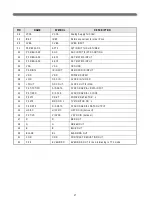
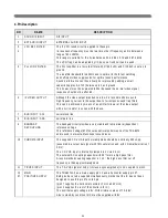
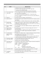
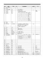
PH I-1 FILTER
The loop filter connected to pin 43 is suitable for various signal conditions
as strong/w eak and VC R signal.
This is achieved by sw itching of the loopfilter tim e constant by changing
the PH I-1 output current.
Via IIC bus FO A/B,different tim e constants can be chosen,including an
autom atic m ode w hich gives optim al perform ance under varing conditions.
44
G R O U N D
To this pin are connected the IC -substrate and horizontal output.
45
EAST-W EST D R IVE
not used.
46
47
VER T. D R IVE+
VERT D R IVE-
The vertical drive has a current output.The output is balanced w hich ensures a
good com m on m ode behavior w ith tem perature and m akes the
output signal less sensitive for disturbances.
48
49
IF IN PU T
The PLL freq. range is 32-60M H z w ith corresponding V C O freq. 64-120M H z.
The IF input im pedance is 2
in parallel w ith 3pF and m atches the required load
for com m only used saw filters.
A D C coupling is allow ed, so no series capacitors betw een saw filter
and IF input are necessary.
50
EH T/O VERVO LTAG E
PR O TEC T IN PU T
not used
51
VER TTIC AL SAW -
TO O TH C APAC ITO R
This pin requires a capacitor to ground of 100nF +/-5% .
The optim al saw tooth am plitude is 3.5V and is determ ined by the external
capacitor and charge current.
The saw tooth bottom -level is 2V.
52
R EFER EN C E C U R -
R EN T IN PU T
This pin requires a resistor to ground.
The optim al reference current is 100
.w hich is determ ined by this resistor.
53
AG C D EC O U PLIN G
C APAC ITO R
The AG C capacitor value is 2.2
and has been defined for an optim al
com prom ise betw een AG C speed and tilt for all A G C m odes(+/-m odulation)
54
TU N ER AG C O U TPU T
This output is used to control(reduce) the tuner gain for strong R F signals.
The tuner AG C is an open collector output w hich is acting as a variable current
source to ground.
55
AU D IO D EEM PH ASIS
O nly a capacitor has to be connected to this pin that defines the deem phasis tim e
constant. The signal is internally connected through to the Audio sw itch.
The capacitor can be calculated as follow s.
56
SO U N D D EC O U PLIN G
This pin requires a capacitor of 10
connected to ground.
The pin acts as a low pass filter needed for the D C feedback loop.
N O
N A M E
D E S CR IPTIO N
Содержание MV1421
Страница 1: ...SERVICE MANUAL MV1421 1422 4822 34cm 48cm Televideo Effective December 1999 MV4822SERV ...
Страница 6: ...4 3 BLOCK DIAGRAM 3 1 Audio Signal Flow ...
Страница 7: ...5 3 2 Video Signal Flow ...
Страница 8: ...6 3 3 TV and monitor power switching ...
Страница 22: ...20 3 Block Diagram ...
Страница 53: ......
Страница 54: ......
Страница 55: ......
Страница 117: ...2 Main PCB Assy Circuit Diagram SECTION BEFORE AFTER MAIN TUNER ...
Страница 118: ...3 SECTION BEFORE AFTER SUB TUNER ...
Страница 125: ...10 Exploded View MV1421 model ...
Страница 126: ...11 Exploded View MV1422 model ...
Страница 127: ...12 Exploded View MV4822 model ...
Страница 128: ...13 Exploded View DVT 20F9 model ...
Страница 129: ...14 Exploded View DVT 21F1 model ...
Страница 130: ...15 Exploded View DVT 21F2 model ...

