18
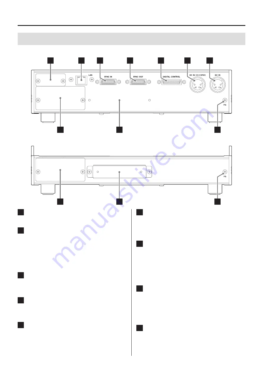
4-2. Back
Main unit (LX-1000)
A
B
C
D
E
F
G
H
I
J
Expansion unit (AU-LX1000EPIO)
H
I
J
4. Names and functions of parts
A
Option slot
This slot is for options.
B
LAN (1000BASE-T) connector
This is for an Ethernet connection. Use to connect
the system with a computer.
The left LED lights when linked.
The right LED blinks when transmitting data.
o
Use a category 7 LAN cable.
C
SYNC IN connector for synchronized recording
Use to synchronize recording. Do not connect any-
thing when not conducting synchronized recording.
D
SYNC OUT connector for synchronized recording
Use to synchronize recording. Do not connect any-
thing when not conducting synchronized recording.
E
DIGITAL CONTROL input/output connector for
external control
Use to control recording and playback with contact
signals and to connect a remote control unit (option).
F
Expansion unit DC power input (DC IN (2-3
EPIO)) connector
When using two or three AU-LX1000EPIO expansion
units, use to input a power supply of 8–36 V.
G
DC IN power input connector
Connect the included AC adapter here.
Use the optional DC power cable designed for this
unit to supply DC 8–36V power. This can power the
main unit (LX-1000) and a single expansion unit
(AU-LX1000EPIO).
H
Cooling fan installation panels
When using two or three AU-LX1000EPIO expan-
sion units, install cooling fans in the units.
o
When using any number of AR-LXST1000 modules,
install a cooling fan.
I
Connector covers
When using expansion units, attach the connector
covers removed from the bottom of the main unit
and the tops of the expansion units here for storage.


