background image

4

PROTECTION AND LOCATION OF YOUR SET

11.

Do not use this television set near water ... for example, near a bathtub, washbowl, kitchen sink, or laundry tub, in a

wet basement, or near a swimming pool, etc.

Never expose the set to rain or water.  If the set has been exposed to rain or water, unplug the set from the wall

outlet and refer servicing to qualified service personnel.

12. Choose a place where light (artificial or sunlight) does not shine directly on the screen.

13. Avoid dusty places, since piling up of dust inside TV chassis may cause failure of the set when high humidity persists.

14. The set has slots, or openings in the cabinet for ventilation purposes, to provide reliable operation of the receiver, to

protect it from overheating.  These openings must not be blocked or covered.

Never cover the slots or openings with cloth or other material.
Never block the bottom ventilation slots of the set by placing it on a bed, sofa, rug, etc.
Never place the set near or over a radiator or heat register.
Never place the set in 

enclosure, unless proper ventilation is provided.

PROTECTION AND LOCATION OF YOUR SET

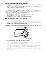
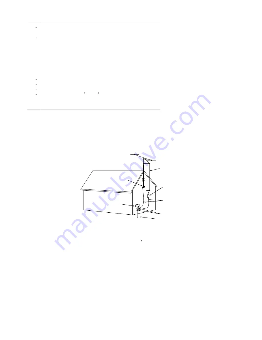
15.1. If an outside antenna is connected to the television set, be sure the antenna system is grounded so as to provide some

protection against voltage surges and built up static charges, Section 810 of the National Electrical Code, NFPA No.
70-1975, provides information with respect to proper grounding of the mast and supporting structure, grounding of the
lead-in wire to an antenna discharge unit, size of grounding conductors, location of antenna discharge unit, connection
to grounding electrode, and requirements for the grounding electrode.

15.2. Note to CATV system installer : (Only for the television set with CATV reception)

This reminder  is provided to call  the CATV system 

attention  to  Article  820-40  of  the  NEC  that  provides

guidelines for  proper grounding and, in particular, specifies that the cable ground shall be connected to the grounding
system of the building, as close to the point of cable entry as practical.

16.

An outside antenna system should not be located in the vicinity of overhead power lines or other electric lights or power
circuits, or where it can fall into such power lines or circuits.  When installing an outside antenna system, extreme care
should be taken to keep from touching such power lines or circuits as contact with them might be fatal.

17.

For added protection for this television set during a lightning storm, or when it is left unattended and unused for long
periods of time, unplug it from the wall outlet and disconnect the antenna.  This will prevent damage due to lightning
and power-line surges.

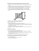
ANTENNA
LEAD- IN WIRE

ANTENNA DISCHARGE
UNIT (NEC SECTION
810-20)

GROUNDING
CONDUCTORS
(NEC SECTION 810-21)

GROUND CLAMPS

POWER SERVICE GROUNDING
ELECTRODE SYSTEM
(NEC ART 250. PART H)

ELECTRIC SERVICE

EQUIPMENT

GROUND CLAMP

NEC-NATIONAL ELECTRICAL CODE

EXAMPLE OF ANTENNA GROUNDING AS PER

NATIONAL ELECTRICAL CODE

EXAMPLE OF ANTENNA GROUNDING AS PER NATIONAL ELECTRICAL CODE INSTRUCTIONS

a   built-in

installer s

Содержание CT-F5151

Страница 1: ...SERVICE MANUAL CTF5151 51CM CTV MAR04 SERVCTF5151 ...

Страница 2: ...nment Procedure 29 5 Block Diagram 36 6 Schematic Diagram 37 7 PCB Layout 38 8 Explode Diagram 39 This manual is the latest at the time of printing and does not include the modification which may be made after the printing by the constant improvement of product EC 21166 ...

Страница 3: ...ce of uninsulated voltage within the products enclosure that may be of sufficient magnitude to constitute a risk of electric shock to the person The exclamation point within an equilateral triangle is intended to alert the user to the presence of important operating and maintenance servicing instructions in the literature accompanying the appliance CAUTION Use of controls adjustments or procedures...

Страница 4: ...onnel 8 Do not subject your television set to impact of any kind Be particularly careful not to damage the picture tube surface 9 Unplug this television set from the wall outlet before cleaning Do not use liquid cleaners or aerosol cleaners Use a damp cloth for cleaning 10 1 Do not place this television set on an unstable cart stand or table The television set may fall causing serious injury to a ...

Страница 5: ...pporting structure grounding of the lead in wire to an antenna discharge unit size of grounding conductors location of antenna discharge unit connection to grounding electrode and requirements for the grounding electrode 15 2 Note to CATV system installer Only for the television set with CATV reception This reminder is provided to call the CATV system attention to Article 820 40 of the NEC that pr...

Страница 6: ... 21 If you are unable to restorenormal operation by following the detailedprocedurein your operating instructions do not attempt any further adjustment Unplug the set and call your dealer or service technician 22 Whenever the television set is damaged or fails or a distinct change in performance indicates a need for service unplug the set and have it checked by a professional service technician 23...

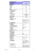
Страница 7: ... DV CRT RF Screen Format 4 3 Size Visual size vis cm 21 Deflection System CRT only Tube Technology CRT only Black Matrix Iron CRT Defl CRT Gun Stand Gun CRT Magn field Neutral Resolution Coating only for D V sets White Point Sound RMS Power Intern RMS Power Extern Surround Sound Sound Features Mute Sound Control Volume Sound Speakers Speaker configuration 2 Speakers used Normal Speaker Size User I...

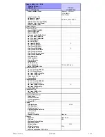
Страница 8: ...bwoofer Dig Audio Out Loudspeakers Control Busses Feature Slot ITV Smart Port Terr Antenna in 75 Ohms IEC type Guide IR Blaster Jack Connectors Front In Y C Cinch CVBS St In Y C Cinch Stereo In Cinch CVBS St Mo In Cinch CVBS Mo Headphone Out Feature Slot Connectors Side In Y C Cinch CVBS St In Y C Cinch Stereo In Cinch CVBS St Mo X IN Cinch CVBS Mo Headphone Out Connectors Top In Cinch CVBS St Hea...

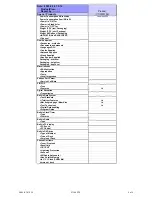
Страница 9: ...ging height cm Packaging depth cm Miscellaneous EAN Indication Approbation Tests Local Integration Various Perf Param Service Call Rate PIP POP Type Features No Digital Reception Transmission Built in Data System Text Standard Tele text Features No Nbr bckgrnd page Mem Size No Text Technology No Digital Data handling Program Guide Built in Clock Timer Type Features Built in Radio Type Built in PC ...

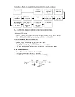
Страница 10: ...5V to mains power input and Philips standard testing pattern to RF input 2 Adjust VR830 in STANDARD mode until voltage at TP2 B is 112V 0 5V II NICAM Adjustment for NICAM model only 1 Apply a 38 9MHz color bar with NICAM signal to the IF input 2 Monitor the DC voltage at pin 15 of IC1101 3 Adjust T1101 until the voltage at pin 15 of IC1101 becomes 2 5 0 1V 4 Then check the waveform at pin 4 and 6 ...

Страница 11: ... 3 Enter D mode and press MUTE key and the screen will become a horizontal line Then adjust the SCREEN VR on the flyback transformer to set the intensity of the line to a minimum visible level the line can just be seen 4 Press MUTE key again and the TV will become full raster 5 Select BRTC to adjust the sub brightness until that the 2nd dark bar of 8 level grey scales just can be seen VI Adjustmen...

Страница 12: ...LIS to adjust the vertical linearity 6 Select VSS to adjust the vertical S correction X Adjustment of OSD position 1 Enter D mode and press key 1 then choose OSDH OSDHS item and adjust the OSD vertical position 50HZ 60HZ 2 Enter D mode and press key NOTE then choose the OSD1 item and adjust the OSD horizontal position Volume bar Picture bar Half blue panel OSD 3 Enter D mode and press key NOTE the...

Страница 13: ...CNTX CONTRAST MAX CNTN CONTRAST MIN BRTX BRIGHT MAX difference from center BRTN BRIGHT MIN difference from center COLX COLOR MAX difference from center COLN COLOR MIN TNTX TINT MAX difference from center TNTN TINT MIN difference from center GROUP 4 KEY 4 BRTC BRIGHT CENTER COLC COLOR CENTER NTSC COLS COLOR CENTER SECAM COLP COLOR CENTER PAL shift data from COLC SCOL SUB COLOR Cr input 21 gain up S...

Страница 14: ... readjust when position select 0 enable 1 disable FLG1 0 1 7 key 0 6 key 1 Secam 0 disable 1 enable 2 LOGO 0 disable 1 enable 3 TINT por 4 PIF SELECT 01 45 75 MHZ 5 011 38 9MHZ 6 100 38MHZ 7 APC 1 AUTO 0 PRESET STBY 0 1 2 3 hd kill timer set 40us 4 when STBY 5 0 after AC on 0 standby 1 power on 5 after AC power on 0 ref STBY 4 1 last state 6 auto sleep function 7 MODE0 0 NICAM 0 DISABLE 1 ENABLE 1...

Страница 15: ...TRAST MAX RGCN TEXT RGB CONTRAST MIN SECD SECAM MODE GROUP 9 KEY 8 V25 VOLUME 25 V50 VOLUME 50 V100 VOLUME 100 GROUP 10 KEY 9 SVM SVM PYNX Normal H SYNC max PYNN Normal H SYNC min PYXS Search H SYNC max PYNS Search H SYNC min GROUP 11 KEY CALENDAR CLTO TV mode SOUND SYS M CLTM TV mode SOUND SYS M CLVO VIDEO CLVD YUV MODE CLTO CLTM CLVO CLVD bit setting 7 KILLER OFF 6 P N ID 5 C GAMMA 4 3 NTSC MATR...

Страница 16: ...l Position volume bar Picture bar Half blue panel OSD OSDF1 OSD PLL DATA volume bar Picture bar Half blue panel OSD OSD2 OSD Horizontal Position except OSD1 items OSDF2 OSD PLL DATA except OSDF1 items HAFC 0 when nois 2 1 TV hafc gain 1 if nois 2 0 TV hafc gain depend on noise 0 1 2 in video mode hafc gain 3 NOIS HAFC DATA 0 noise det 1 2 fix the hafc gain UCOM MCU DATA ...

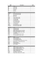
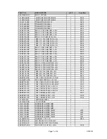
Страница 17: ...X RES M O 2 7K OHM 1 2W 5 1 R514 18 FE0272 JNX RES M O 2 7K OHM 1 2W 5 1 R515 18 FE0272 JNX RES M O 2 7K OHM 1 2W 5 1 R518 18 FG0153 JHX RES M O 15k OHM 2W 5 1 R510 18 FG0153 JHX RES M O 15k OHM 2W 5 1 R511 18 FG0153 JHX RES M O 15k OHM 2W 5 1 R512 26 AIM103 KBX CAP CER 0 01UF 500V 10 B 1 C504 26 AMK221 KBX CAP CER 220PF 2KV 10 B 1 C505 26 EBP103 ZFX CAP CER 0 01UF 50V 80 20 F 1 C514 26 EBP103 ZFX...

Страница 18: ...OHM 1 6W 5 1 R850 18 CD0123 JNX RES C F 12K OHM 1 4W 5 1 R804A 18 CD0220 JNX RES C F 22 OHM 1 4W 5 1 R811A 18 CD0221 JNX RES C F 220 OHM 1 4W 5 1 R833 18 CD0392 JNX RES C F 3 9K OHM 1 4W 5 1 R835 18 CD0471 JNX RES C F 470 OHM 1 4W 5 1 R811 18 CE0479 JNX RES C F 4 7 OHM 1 2W 5 1 R832 18 CE0563 JNX RES C F 56k OHM 1 2W 5 1 R831 18 DD0104 FNX RES M F 0 1M OHM 1 4W 1 1 R804 18 FG0153 JHX RES M O 15k O...

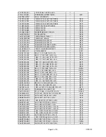
Страница 19: ...RE BARE JUMPER 10MM 1 J822 41 WJ0100 B00 WIRE BARE JUMPER 10MM 1 J827 41 WJ0100 B00 WIRE BARE JUMPER 10MM 1 R807A 41 WJ0105 B00 WIRE BARE JUMPER 10 5MM 1 J824 41 WJ0110 B00 WIRE BARE JUMPER 11MM 2 41 WJ0115 B00 WIRE BARE JUMPER 11 5MM 1 J823 41 WJ0125 B00 WIRE BARE JUMPER 12 5MM 1 J804 41 WJ0125 B00 WIRE BARE JUMPER 12 5MM 1 J808 41 WJ0125 B00 WIRE BARE JUMPER 12 5MM 1 J832 41 WJ0145 B00 WIRE BARE...

Страница 20: ...25 BDA471 M1X CAP ELEC 470 UF 25V 20 1 C843 08 0D181H FC2 ASS Y FRONT CAB LS PM 02 GND021 XX0 ASS Y CRT GND WIRE HOUSE 1 36 DEG210 BX3 DEGAUSSING COIL 2500mm 1 42 51208D AX1 SPEAKER 5W 8 OHM 1 W601 42 51208D AX1 SPEAKER 5W 8 OHM 1 W602 44 21RFLS PM2A 21 CRT A51LYZ095X90 1 CRT01 46 27250H 02X HS 2P24 450 5 F W TJC3 02H 1 46 37144H 02X HS 2P 2468 22 450mm S11 2Y 7mm 1 54 113970 0U0 PVC TUBE 5 L ROLL...

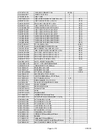
Страница 21: ...SCN 4Y 1 48 TAC001 XX0 TACT SWITCH 1 S001A 48 TAC001 XX0 TACT SWITCH 1 S002A 48 TAC001 XX0 TACT SWITCH 1 S003A 48 TAC001 XX0 TACT SWITCH 1 S004A 48 TAC001 XX0 TACT SWITCH 1 S005A 48 TAC001 XX0 TACT SWITCH 1 S006A 02 IRR001 XX1 IR RECEIVER MODULE HRM380017 1 IR001 08 0D181H RC2 ASS Y REAR CAB 94V0 RCA 54 114000 00X FELT TAPE 150mmX19mmX0 3mm 7 55 D189RC 1AN REAR CABINET 1 58 D106SI 3UI INLAY SIDE A...

Страница 22: ...M 1 6W 5 1 R1502 18 CB0229 JNX RES C F 2 2 OHM 1 6W 5 1 R1501 25 HBB479 M1X CAP ELEC 4 7 UF 10V 20 1 C1502 26 EBP101 JCX CAP CER 100PF 50V 5 CH 1 C1503 26 EBP101 JCX CAP CER 100PF 50V 5 CH 1 C1504 40 113SLF RMB P C B REMOTE HANDSET BD 1 41 WJ0070 B00 WIRE BARE JUMPER 7MM 1 J1501 45 COS455 KY1 CERAMIC RESONATOR 455KHz 1 X1501 49 HS46F0 00X RUBBER PAD KEYS 1 55 HS46FB 0HA CASE LOWER REMOTE HANDSET 1...

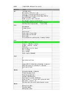
Страница 23: ...STOR 2SC2482 1 Q401 11 SC3779 DBX TRANSISTOR 2SC3779D RF AMPL 1 Q101 13 000040 66P IC 4066 ANALOG SW 1 IC603 13 00M24C 08P IC EEPROM 8K M24C08 1 IC001 13 L7809C VAP IC L7809CV 1 IC401 13 LA7840 00S IC LA7840 1 IC301 13 TDA705 7AS IC TDA7057AQ R L AUDIO O P 1 IC601 18 CB0101 JNX RES C F 100 OHM 1 6W 5 1 R001A 18 CB0101 JNX RES C F 100 OHM 1 6W 5 1 R033 18 CB0101 JNX RES C F 100 OHM 1 6W 5 1 R034 18...

Страница 24: ...20k OHM 1 6W 5 1 R206 18 CB0271 JNX RES C F 270 OHM 1 6W 5 1 R233 18 CB0273 JNX RES C F 27k OHM 1 6W 5 1 R922A 18 CB0303 JNX RES C F 30K OHM 1 6W 5 1 R205 18 CB0331 JNX RES C F 330 OHM 1 6W 5 1 R219 18 CB0331 JNX RES C F 330 OHM 1 6W 5 1 R228 18 CB0331 JNX RES C F 330 OHM 1 6W 5 1 R227 18 CB0331 JNX RES C F 330 OHM 1 6W 5 1 R220 18 CB0332 JNX RES C F 3 3k OHM 1 6W 5 1 R218A 18 CB0332 JNX RES C F 3...

Страница 25: ...CE0331 JNX RES C F 330 OHM 1 2W 5 1 R409 18 CE0560 JNX RES C F 56 OHM 1 2W 5 1 R317 18 EF0109 JGX RES FUS 1 OHM 1W 5 LS 1 R403 18 EF0109 JGX RES FUS 1 OHM 1W 5 LS 1 R405 18 EF0109 JGX RES FUS 1 OHM 1W 5 LS 1 R418 18 EG0339 JHX RES FUS 3 3 OHM 2W 5 1 R407 18 FF0103 JGX RES M O 10k OHM 1W 5 1 R410 18 FF0472 JGX RES M O 4 7K OHM 1W 5 1 R441 18 FF0123 JGX RES M O 12k OHM 1W 5 1 R408 18 FF0221 JGX RES ...

Страница 26: ...C 4 7 UF 50V 20 1 C602 25 BFB479 M1X CAP ELEC 4 7 UF 50V 20 1 C603 25 BHB100 M1X CAP ELEC 10 UF 100V 20 1 C420 25 BLA100 M1X CAP ELEC 10 UF 250V 20 1 C408 26 AIC102 KBX CAP CER 1000 PF 500V 10 B 1 C401 26 AIC102 KBX CAP CER 1000 PF 500V 10 B 1 C404 26 AIC332 KBX CAP CER 3300 PF 500V 10 B 1 C407 26 AIC391 KBX CAP CER 390 PF 500V 10 B 1 C409 26 AIC391 KBX CAP CER 390 PF 500V 10 B 1 C412 26 EBP100 JC...

Страница 27: ... P E 0 1 UF 63V 5 1 C610 27 PBA224 J0X CAP P E 0 22UF 63V 5 1 C105 27 PBC103 J0X CAP P E 0 01UF 63V 5 1 C215 27 PBC152 J0X CAP P E 0 0015UF 63V 5 1 C209 27 PBC222 J0X CAP P E 0 0022UF 63V 5 1 C213 27 PBC222 J0X CAP P E 0 0022UF 63V 5 1 C204 27 PBC272 J0X CAP P E 0 0027UF 63V 5 1 C210 27 PBC472 J0X CAP P E 0 0047UF 63V 5 1 C607 27 PBC472 J0X CAP P E 0 0047UF 63V 5 1 C608 27 PBC473 J0X CAP P E 0 047...

Страница 28: ...MM 1 J305 41 WJ0065 B00 WIRE BARE JUMPER 6 5MM 1 J908 41 WJ0065 B00 WIRE BARE JUMPER 6 5MM 1 J913 41 WJ0065 B00 WIRE BARE JUMPER 6 5MM 1 J920 41 WJ0065 B00 WIRE BARE JUMPER 6 5MM 1 R311 41 WJ0065 B00 WIRE BARE JUMPER 6 5MM 1 J911 41 WJ0070 B00 WIRE BARE JUMPER 7MM 1 J104 41 WJ0070 B00 WIRE BARE JUMPER 7MM 1 J307 41 WJ0070 B00 WIRE BARE JUMPER 7MM 1 J906 41 WJ0070 B00 WIRE BARE JUMPER 7MM 1 J015 41...

Страница 29: ...M 1 J204 41 WJ0130 B00 WIRE BARE JUMPER 13MM 1 J211 41 WJ0135 B00 WIRE BARE JUMPER 13 5MM 1 J006 41 WJ0135 B00 WIRE BARE JUMPER 13 5MM 1 J215 41 WJ0150 B00 WIRE BARE JUMPER 15MM 1 C406A 41 WJ0150 B00 WIRE BARE JUMPER 15MM 1 L402 41 WJ0150 B00 WIRE BARE JUMPER 15MM 1 J112 41 WJ0165 B00 WIRE BARE JUMPER 16 5MM 1 J220 41 WJ0165 B00 WIRE BARE JUMPER 16 5MM 1 J302 41 WJ0175 B00 WIRE BARE JUMPER 17 5MM ...

Страница 30: ...1X CAP ELEC 47 UF 160V 20 1 C411 67 H10918 4M2 HEAT SINK 1 67 H10918 4M2 HEAT SINK 1 26 EBP471 JCX CAP CER 470PF 50V 5 CH 1 C008 25 BCB221 M1X CAP ELEC 220 UF 16V 20 1 C231 41 WJ0065 B00 WIRE BARE JUMPER 6 5MM 1 J108 13 A19V04 TOP IC A19V04 TO 1 IC201 25 GFB228 K1X CAP ELEC 0 22 UF 50V 10 1 C205 25 GFB478 K1X CAP ELEC 0 47 UF 50V 10 CEC K 1 C236 27 RCP333 J0X CAP PP 0 033 UF 100V 5 1 C405 25 GFB47...

Страница 31: ...v 12V 12V Tuner TU101 IF AMP Q101 SAW Z101 TMPA8821 IC201 Q501 Q503 Q505 AMP R G B CRT R G B V AMP IC301 V out H drive AMP Q401 Q402 H out FBT T402 220V 24V 6 3V EHT FOCUS SCREEN CPU IC001 E2 PROM IC002 KEY IR001 Sensor AV Vin IC603 TV AV SW Audio AMP IC601 AV Aout AV Vout Speaker AV Ain ...

Страница 32: ......

Страница 33: ......

Страница 34: ......

Отзывы: