1 2 3 Remarks
- - x
Master
: The Drive is configured as first IDE drive
(basic setting). This configuration can be used only if
the Drive is connected to the
second
IDE controller
(secondary IDE). If a hard disk is already operated at
the secondary IDE controller (configured as master)
the jumper setting at the drive has to be changed to
slave.
- X -
Slave:
The drive is configured as second IDE drive. If
there is only one hard disk in the PC the optical drive
can be operated at the same IDE connection parallel
to this hard disk. Important: The data rates of both
devices may be decreased.
X - -
Cable Select:
Master/slave detection is achieved by
the controller.
Installation and Connection
Very important:
Switch off your PC and any attached
devices and disconnect the power cord(s).
It is not sufficient to switch off the power
switch! Do the same if the optical drive is
reconfigured.
(1)
Open the case of your PC and lift it off carefully.
(2)
Configure the optical drive if necessary.
(3)
Locate a free slot for 13.3cm / 5.25” drives and
install the Drive using the provided four screws.
Important:
Do not use screws which are longer than 5 mm!
(4)
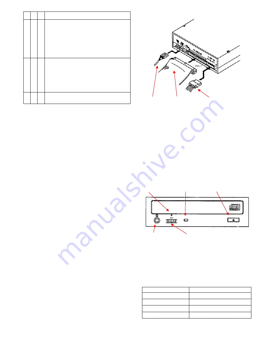
Connect the power cable and the 40-pin data cable
(assure the correct orientation, pin 1 is often
marked with a color stripe) to the drive. Connecting
in the wrong orientation may damage the drive and
the
_
PC!
(5)
Connect the provided audio cable to the sound
card.
Usually sound cards offer more than one connector
to connect an audio cable to. Please refer to the
manual of the sound card to find the connector in
question.
Audio-Cable 40-pin Datakabel Power Cable
(6)
Close the case of the PC. Do not forget to connect
other devices and accessories if there are any.
(7)
Connect the PC to the wall outlet and switch it on
Important:
If your PC will not start up correctly switch it off
immediately and check all of the connections
and jumper settings.
Controls and Functions at the Front Panel
Emergency Eject Busy-LED Eject Key
Headphone Jack Volume-Control
ON/BUSY indicator
The indicator LED light in Seek, Play, Read, and Write
operation. In the following table you will find a list
including a description of the different drive states and
their associated indicator states.
Operation LED
Write
Red LED lights
Audio Play
Green LED flashes
Seek/Data Transfer
Green LED lights
At start
Green LED flashes


