background image

6

7

2.2 

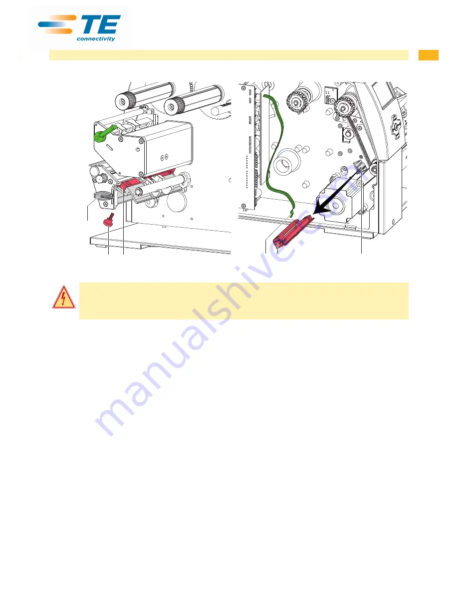
Cleaning the Label Sensor 

1

5

2

4

2

3

Fig. 1 

Cleaning the label sensor  


Fig 2 

Removing the label sensor

Danger!

Risk of death via electric shock!


X

Before opening the housing cover, disconnect the device from the mains supply and wait at lease one 

minute until the power supply unit has discharged.

1.  Remove media from the printer.
2.  Remove the Allen key (5) from its retainer.
3.  Remove the rear cover of the printer.
4.  Unscrew knurled thumb screw (1).
5.  Unplug the cable (3) from the plug on the rear end of the label sensor (2).
6. 

Push the label sensor (2) so deep as possible into the guide profile toward  the chassis.

7.  Slide out the label sensor assembly (2) toward the back side cover.
8.  Clean label sensor and sensor units (2) with brush or cotton swab soaked in pure alcohol. 
9.  Push label sensor back toward the print head side of printer so you can see the hole in the label sensor over the 

long hole in the profile (guide).

10. Connect the cable (3) to the label sensor (2).
11. Attach knurled thumb screw (1).
12. Pull the label sensor (2) via knurled thumb screw (1) so far as possible toward cover side. This prevents the cable 

(3) from being pinched when installing the rear cover.

13. Install the rear cover of the printer.
14. Adjust label sensor  

 

operators manual.

15. Insert the Allen key (5) into its retainer.

2 Cleaning

Содержание TE3112

Страница 1: ...PB Service Manual TE3124 TE3112 Thermal Transfer Printer...

Страница 2: ...any 49 0 173 3169004 Email ident tech support te com Ireland Toll Free 800 557 810 Phone is monitored in the afternoon local time Email ident tech support te com Rest of Europe http www te com help Em...

Страница 3: ...acing Label Sensor 14 3 7 Replacing the PCB CPU 15 3 8 Replacing the Power Supply Unit 16 4 Adjustments 17 4 1 Measuring and Adjusting the Winding Torques 17 4 1 1 Measuring the Winding Torques 17 4 1...

Страница 4: ...device X X Do not wear clothing with metal parts X X Do not wear jewelry X X Do not wear spectacles with metal frames Warning Items of clothing drawn into the device by moving parts can lead to injur...

Страница 5: ...ing circuits in the device Test the zero potential of the device parts Check the working area for possible sources of danger such as wet floors defective extension cables defective protective conducto...

Страница 6: ...the device cleaning the printhead cleaning the print roller cleaning the label sensor Danger Risk of death via electric shock X X Before opening the housing cover disconnect the device from the mains...

Страница 7: ...2 so deep as possible into the guide profile toward the chassis 7 Slide out the label sensor assembly 2 toward the back side cover 8 Clean label sensor and sensor units 2 with brush or cotton swab soa...

Страница 8: ...tion The plastic cover can be damaged via careless handling X X Do not use force X X Do not twist the plastic cover when removing it or pressing it on Fig 3 Removing and installing the plastic cover R...

Страница 9: ...g line 6 Pins 7 Printhead Fig 4 Structure of the printhead Attention The printhead 7 is adjusted on a head plate 1 and precisely aligned at the factory Do not loosen the screws 4 under any circumstanc...

Страница 10: ...d from the printhead mounting bracket 9 if necessary 7 Loosen both plug connections 2 3 on the printhead and set printhead down on a clean soft surface Installing the printhead 1 Attach plug connectio...

Страница 11: ...Fig 6 Slipping clutches Danger Risk of death via electric shock X X Before opening the housing cover disconnect the device from the mains supply and wait at lease one minute until the power supply uni...

Страница 12: ...l sensor toward the cover side as far as possible and install the rear cover of the printer Installing the brake on the transfer ribbon supply hub 12 7 11 9 4 10 4 Snap ring 7 Winder axis 9 Brake 10 L...

Страница 13: ...nto the tab 4 toward the rear cover until it stops 5 Unplug the cable 2 from the plug on the rear end of the label sensor 1 6 Unscrew the screws 5 with an Allen key and remove the side plate 7 7 Pull...

Страница 14: ...sor 2 so deep as possible into the guide profile toward the chassis 6 Slide out the label sensor assembly 2 toward the back side cover Installing the label sensor 1 Push label sensor back toward the p...

Страница 15: ...Remove the PCB CPU Fig 11 Removing the PCB CPU 4 5 6 7 8 9 10 Fig 12 Used connectors on the PCB CPU 4 Control panel 5 Peripheral port 6 Sensors 7 Printhead signals 8 Printhead power supply 9 Power su...

Страница 16: ...t input 3 6 Unplug the plug at the power supply unit output 1 7 Remove the two screws on the back of the printer 7 8 Hold the power supply unit firmly at the metal bracket 4 and remove the two screws...

Страница 17: ...ons The measured clockwise torque is the sum of the coupling torque and the torque of the brake Only the torque of the brake is measured when the winding axis is rotating counter clockwise For this re...

Страница 18: ...y unit has discharged 1 Unplug the printer from the electrical outlet 2 Remove the rear cover 3 Remove the transfer ribbon from the printer 4 Attach the test collar 3 to the winder 4 5 Turn the knurle...

Страница 19: ...t the device from the mains supply and wait at lease one minute until the power supply unit has discharged 3 1 2 4 1 Unplug the printer from the electrical outlet 2 Remove the rear cover 3 Remove the...

Страница 20: ...ly unit has discharged 2 1 1 Unplug the printer from the electrical outlet 2 Remove the rear cover 3 Press the knurled ring 1 of the slipping clutch toward the housing wall The lock 2 of the knurled r...

Страница 21: ...inting mechanism comprises the following procedures in the order specified 1 Prepare the label printer for adjustment 4 2 1 on page 21 2 Adjust the position of the printhead 4 2 2 on page 22 3 Adjust...

Страница 22: ...ment 1 Check the alignment of the printhead in the adjustment windows 1 2 If the printhead is not aligned properly loosen the screw 3 about one quarter turn 3 If the printhead is not aligned properly...

Страница 23: ...barely recognizable Under these conditions inaccuracies become clearly visible during adjustment 3 Create print samples with the test function Test grid or a similar print pattern 4 Adjust the adjustm...

Страница 24: ...der as the supply roll is from the disk of the supply hub 2 If the ribbon runs inward or outward turn the corre sponding screw 3a or 3b clockwise in small increments 3 Wait until the ribbon feed path...

Страница 25: ...rub against the label sensor during printing which would damage the belt X X Tension the toothed belt in such a way that it cannot rub against the label sensor 3 4 2 1 1 Unplug the printer from the el...

Страница 26: ...the power supply unit has discharged 1 2 3 2 3 1 Unplug the printer from the electrical outlet 2 Remove the rear cover 3 Lock printhead 4 Slightly loosen the fixing screws 3 of the head switch 2 5 Mov...

Страница 27: ...point The power supply unit may be defective Replace the power supply unit No voltage at one measurement point The PCB CPU may be defective Replace the PCB CPU Replace LCD Display cpl Replace PCB Nav...

Страница 28: ...tage too low Replace the power supply unit Voltage is correct Replace the PCB CPU 24 V 24 V too low Check voltage at measurement point 24V Fig 25 on page 31 Voltage too low Replace the power supply un...

Страница 29: ...6 Block Diagram Printer Type Nr 1 Nr 2 Nr 3 Nr 4 Nr 5 Nr 6 TE3112 TE3124 300dpi 5954072 5954067 5954066 5946208 5954099 5958670 600dpi 5954077 5954067 5954066 5946208 5954099 5958670 Fig 23 Block dia...

Страница 30: ...30 30 7 Layout Diagram PCB CPU Fig 24 Layout diagram PCB CPU components side...

Страница 31: ...30 31 7 Layout Diagram PCB CPU Fig 25 Layout diagram PCB CPU soldering side...

Страница 32: ...re faults 28 I Internal rewinder winding torque 19 L Label sensor cleaning 6 7 replacement 14 Layout diagram PCB CPU 31 P Printhead replacing 9 Procedure in case of accidents 5 Protective devices 4 Pu...

Отзывы: