background image


409-32043 

Rev. D 

of 11 


Installing the die assemblies 

1.  Remove the battery from the crimping tool. 

2.  Remove the two die retaining screws from the crimp jaws. 

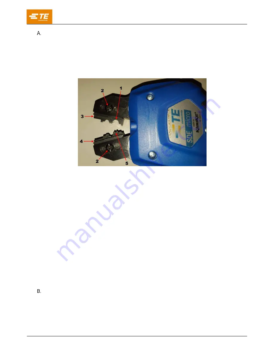
3.  Slide the upper die into the jaw. Orient the die so that the indenters face inward (with the largest 

indenter entering first) and the screw holes align (Figure 2)

Figure 2: Inserting the dies 


Largest anvil 

Retaining screw 

Lower die 

Upper die 

Largest indenter 

4.  Insert the die retaining screw into the screw hole of the jaw. Tighten the screw just enough to hold 

the die in place. Do 

not

 tighten the screw completely. 

5.  Slide the lower die into the other jaw. Orient the die so that the anvils face inward (with the largest 

anvil entering first) and the screw holes align (Figure 2)

6.  Insert the lower die retaining screw into the screw hole of the jaw and through the screw hole of 

the lower die. Tighten the screw just enough to hold the die in place. Do 

not

 tighten the screw 

completely. 

7.  Squeeze the trigger lever to slowly close the dies, making sure the crimping chambers are 

properly aligned. 

8.  When the crimping chambers are aligned, tighten the die retaining screws. 

9.  Re-install the battery. 

10.  Cycle the tool to verify that the crimp chambers are properly aligned. 


Removing the die assemblies 

1.  Remove the battery from the crimping tool. 

2.  Remove the die retaining screws. 

3.  Slide the dies out of the jaws of the crimping head. 

Содержание 2280380 Series

Страница 1: ...atest revision and Regional Customer Service visit our website at www te com 409 32043 30 SEP 2021 Rev D INTRODUCTION 5 RECEIVING AND INSPECTION 7 PRE OPERATION TESTING 7 OPERATION 8 Installing and re...

Страница 2: ...ersonnel Failure to observe this warning can result in severe injury or death CAUTION Do not place the tool in a vise The crimping tool is designed for hand held operation Protect the crimping tool fr...

Страница 3: ...ewelry that may catch in moving parts of the equipment Never alter modify or misuse the equipment SUPPORT CENTER CALL TOLL FREE 1 800 522 6752 UNITED STATES AND PUERTO RICO ONLY Canada 1 800 522 6752...

Страница 4: ...ifications Dimensions Length 253 mm 9 96 in Width 93 mm 3 66 in Depth 64 mm 2 52 in Mass weight with battery 0 96 kg 2 12 lb Acoustic Sound level 70 dBA at 1 m Vibration 2 5 m s2 Crimping capacities M...

Страница 5: ...result in moderate or severe injury CAUTION Denotes a condition that may result in product or equipment damage NOTE Highlights special or important information Each kit is designed to accept interchan...

Страница 6: ...ell commercial pin and socket contacts 30 24 AWG 0 05 0 2 mm2 90870 2 24 18 AWG 0 2 0 9 mm2 90869 2 MR pin and socket contacts 26 18 AWG 0 13 0 9 mm2 58514 2 Universal MATE N LOK II and Universal MATE...

Страница 7: ...s PRE OPERATION TESTING White LED work light This LED automatically turns on when the trigger is pulled The indicator remains lit for ten seconds after the trigger is released Red LED indicator The to...

Страница 8: ...age the battery lock by applying pressure on the lock toward the bottom of the crimping tool and slide the battery away from the tool DANGER Always dispose of the old battery in an environmentally res...

Страница 9: ...wer die into the other jaw Orient the die so that the anvils face inward with the largest anvil entering first and the screw holes align Figure 2 6 Insert the lower die retaining screw into the screw...

Страница 10: ...wire in position press and hold the trigger closed to complete the crimp When the crimp is complete the crimping tool returns automatically to the first position of its cycle 5 Release the trigger CA...

Страница 11: ...r damaged Return the tool to TE for evaluation REPLACEMENT AND REPAIR DANGER To avoid personal injury always remove the battery from the tool before performing any maintenance on the crimping tool Kit...

Отзывы: