background image

114-151049 

Rev A


of 11


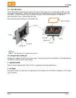
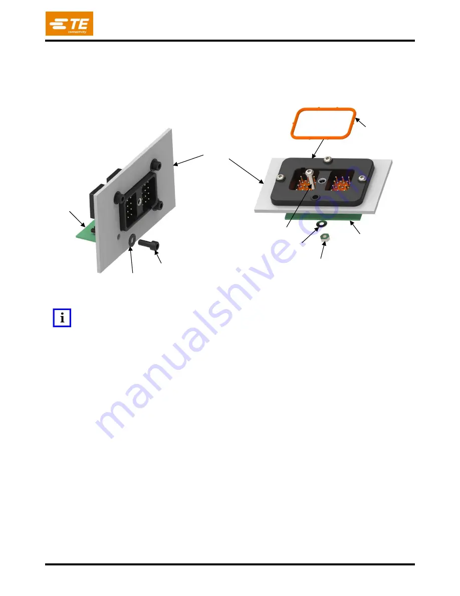
3.11. Panel Mounting 

Insert the header through the panel cutout then secure the header using 10-32 hardware (M5 for C023 
and CG01 modifications).  DRC10-24P requires 0510-014-2406 flange seal (sold separately). Mounting 
hardware (i.e. screw, washer, nut) are customer supplied.  Screw length depend on application. 

Recommended torque:  2.26-2.83 [20-25 in-lbf]. 

Recommended panel thickness is 6.25 [.250] max. 


Note:  
1)


Mounting torque not to damage connector or panel 

3.12. Replacement and Repair 

Damaged or defective header must not be used. It may be removed from the PCB by normal desoldering 
methods and replaced with a new header. 

4.  QUALIFICATION 

Refer to product specificatio

108-151018

 for qualification and approved agency. 

5.  TOOLING 

No special tooling is required for hand placement of the header onto the PCB or installation of the mating 
plug connector. 


PCB 

Washer 4X 

Screw 4X 

PCB 

Screw 4X 

Washer 4X 

Nut 4X 

Panel 

0510-014-2406 

Содержание DRC10-24PX

Страница 1: ...are not drawn to scale 1 INTRODUCTION This specification covers the requirements for application of DEUTSCH DRC16 header connector to be mounted on a printed circuit board PCB The header is offered i...

Страница 2: ...ection 2 3 2 REFERENCE MATERIAL 2 1 Revision Summary See section 7 2 2 Customer Assistance See Section 3 3A for Part Numbering System Product Code EQ78 is representative of DEUTSCH DRC10 and DRC13 ser...

Страница 3: ...N NI CU A B C D 2 4 Specifications 108 151018 Product Specification DRC16 Series Connector System 114 151018 Application Specification DRC16 Series Connector System 2 5 Manuals 402 40 Solderability an...

Страница 4: ...Materials Header Housing PPS GF40 black Pin Spacer PTFE white Flange Seal VMQ red orange Pin Seal VMQ red orange Pin Contact Brass Pin Plating DRC10 Mating Side Sn Ni Cu PCB Side Sn Ni Cu Pin Plating...

Страница 5: ...outside rows are Gold All other Tin G002 Pins on outside rows are Gold All other Tin 3 4 Printed Circuit Board PCB Layout The recommended PCB layout requirement is shown below for the component side T...

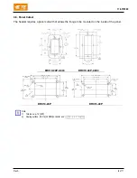
Страница 6: ...anel Cutout The header requires a panel cutout that allows the flange to be mounted on the inside of the panel Note 1 Tolerance 12 005 2 Sealing surface 0 8 Ra 32 RMS or better and DRC10 24P A004 DRC1...

Страница 7: ...lved flux and other contaminants We recommend cleaning the PCB on its edge If using an aqueous cleaner we recommend standard equipment such as a soak tank or an automatic in line machine When drying c...

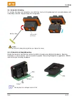
Страница 8: ...damage the plug interface sea Replace if necessary 3 10 Printed Circuit Board Mounting Solder the header to the PCB then secure the DRC13 header using M3 4 40 hardware Mounting hardware i e screw wash...

Страница 9: ...Recommended panel thickness is 6 25 250 max Note 1 Mounting torque not to damage connector or panel 3 12 Replacement and Repair Damaged or defective header must not be used It may be removed from the...

Страница 10: ...h DO NOT appear correct should be inspected using the information in the preceding pages of this specification and in the instruction material shipped with the product or tooling Flange Seal in instal...

Страница 11: ...114 151049 Rev A 11 of 11 7 REVISION HISTORY Rev Brief Description of Change Date Dwn Apvd A Initial Release 13 Nov 2020 DM IG...

Отзывы: