408-9007
2 of 4
Rev A
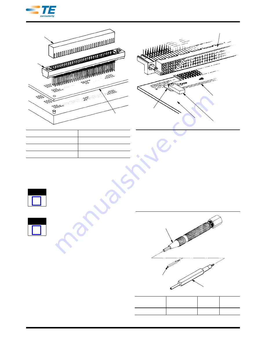
Figure 2
5. Center connector under power unit and cycle
machine to insert connector.
6. Remove connector from power unit.
The maximum allowable gap between seated
connector and pc board is 0.25 mm [.010 in.].
3.2. Receptacle Connectors
(Figure 3)
Receptacle connectors are installed into pc boards
by using Alignment Tool 532925 which aids in the
insertion of the connector into the pc board. The
tool is available in three lengths which incorporate
75, 135, and 180 contact positions, and the tool
features a cam-actuated lever to “open” and “close”
the tool on the receptacle contacts.
Refer to Figure 3 and proceed as follows:
1. Determine number of contact positions in the
assembly being mounted. Make a layout on the pc
board, using the recommended dimensions
provided in Figure 7.
2. Select proper tool, and adjust cam lever to
vertical position to place tool in “open” position.
3. Place contacts in alignment holes of tool, and
adjust lever to horizontal position to “close” the
alignment tool on contacts.
4. Place receptacle contacts through pc board holes
to position connector on pc board.
Figure 3
5. Adjust lever of tool to “open” position and slide
alignment tool from between the connector and pc
board.
6. Fasten connector to the pc board with
appropriate hardware.
7. Solder contacts to pc board using a standard
soldering technique.
4. REPLACING DAMAGED CONTACT
The pin and contact replacement tool, shown in
Figure 4 is used to replace ACTION PIN contacts on
pc boards and panels.
Figure 4
CONNECTOR ROWS
INSERTION TOOL NUMBER
2
58172-1 thru 59172-7
3
58172-8 thru 1-58172-9
4
2-58172-0 thru 3-58172-7
Insertion Tool
Connector
PC Board
NOTE
i
NOTE
i
REPLACEMENT
TOOL
REPLACEMENT
TIP
REMOVAL
TIP
KIT PART
NUMBER
380392-8
308554-1
265964-1
265871-7
Receptacle
Connector
PC Board
Tool Slides Into
Connector
Alignment
Tool
Cam Lever
(Open)
Pin and Contact
Replacement Tool
ACTION PIN Contact
Replacement Tip
ACTION PIN Contact
Removal Tip
Содержание AMP-HDI
Страница 4: ...408 9007 4 of 4 Rev A...


