411-1050
Rev
A
5
of 5
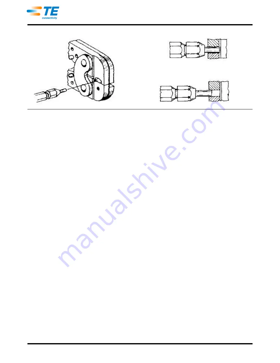
Figure 6
Inspection of Wire Barrel Crimping Dies with Plug Gage
“GO” Gage Must Pass Completely Through the Die Closure
“NO-GO” Gage May Enter Partially, but Must
Not Pass Completely Through the Die Closure
Страница 1: ...he crimping jaws as shown in Figures 3A 3B and 3C 4 Place the PIDG Nylon butt splices in crimping jaws as shown in Figure 4A NOTE For crimping PLASTI GRIP butt splices the locator has to be removed fr...
Страница 2: ...387 7 1 0 2 6 16 14 Blue Green Two Dot PIDG and PLASTI GRIP Terminals Splices and Wire Pins 5 5 219 6 4 250 6 3 250 7 1 281 3 0 3 4 12 187 and 250 Series PIDG FASTON receptacles and Resilient Type PID...
Страница 3: ...pins in next tighter position No 2 d Make a test crimp and repeat adjustment as necessary until the desired insulation grip is obtained e Do not use a tighter setting than required NOTE PLASTI GRIP te...
Страница 4: ...ction Sheet 408 7424 TOOL DIE CLOSURE DIM A GAGE MEMBER DIM A GO NO GO GO NO GO 525690 1 47386 4 2 76 109 2 92 115 2 769 2 776 1090 1093 2 918 2 921 1149 1150 47387 7 3 02 119 3 17 125 3 023 3 029 119...
Страница 5: ...v A 5 of 5 Figure 6 Inspection of Wire Barrel Crimping Dies with Plug Gage GO Gage Must Pass Completely Through the Die Closure NO GO Gage May Enter Partially but Must Not Pass Completely Through the...
Страница 6: ...PRODUCT DATASHEET is brought to you by SOS electronic distribution of electronic components Click to view availability pricing and lifecycle information Visit https www soselectronic com...