


408-1536
Rev J1
6
of 7
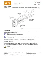
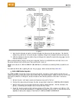
Figure 6
4. Align the NO-GO element and try to insert it straight into the same crimping chamber. The NO-GO
element may start entry, but must not pass completely through the crimping chamber (see Figure 6).
5. With dies bottomed, check insulation (ring) crimping section using the appropriate plug gage in same
manner as Steps 3 and 4.
If
the crimping chamber conforms to the gage inspection, the tool is considered dimensionally correct, and
should be lubricated with a THIN coat of any good SAE 20 motor oil.
If not
, refer to Section 5, REPLACEMENT AND REPAIR, for information on obtaining further evaluation and
repair.
For additional information regarding the use of a plug gage, refer to Instruction Sheet
CERTI-CRIMP Ratchet Inspection
The CERTI-CRIMP tool ratchet on these hand tools should be checked to ensure that the ratchet does not
release prematurely; allowing the dies to open before they have fully bottomed. Obtain a 0.025 mm [.001 inch]
shim that is suitable for checking the clearance between the bottoming surfaces of the dies. Proceed as
follows:
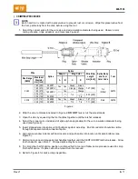
1. Refer to Figure 2, and select a splice and maximum size wire for the tool.
2. Position the splice and wire between the dies, as described in Section 3, CRIMPING PROCEDURE.
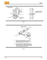
3. Hold the wire in place and squeeze the handles until the ratchet releases. Hold the handles in this
position, maintaining just enough tension to keep the dies closed.
4. Check the clearance between the bottoming surfaces of the dies. If the clearance is 0.025 mm [.001
inch] or less, the ratchet is satisfactory. If clearance exceeds 0.025 mm [.001 in.], the ratchet is out of
adjustment and must be repaired. See Section 5, REPLACEMENT AND REPAIR.
Содержание 46073
Страница 3: ...408 1536 Rev J1 3 of 7 Figure 3 Figure 4 ...


