408-9930
Rev G
3
of 4
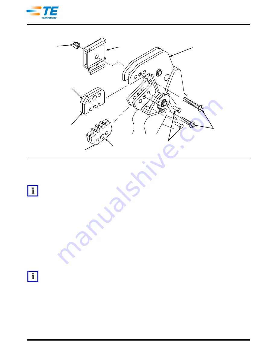
Figure 3
5. Slowly close the tool handles, allowing the dies to mate and/or align. Continue closing the tool handles
until the ratchet makes the seventh
“click”,
then tighten both die retention screws until snug.
NOTE
The tool ratchet has detents that are audible in eight
“clicks”
as the handles are closed. The ratchet releases on the eighth
“click”.
6. Install the locator assembly and tighten the hex nut.
7. Reverse these steps to remove the die assembly.
4.
CRIMP HEIGHT ADJUSTMENT
The tool frame features a ratchet mechanism and adjustment wheel with a range of settings. The ratchet
mechanism ensures that the tool has completed the cycle. The adjustment wheel controls the amount of handle
pressure exerted on the jaws and dies during the crimping procedure. Although the ratchet is preset prior to
shipment, it is important that the crimp height be verified. Also, general use and subsequent wear may cause
the tool to go out of adjustment.
It is recommended that the crimp height be inspected and adjusted, if necessary, on a regular basis by quality
control personnel.
NOTE
This is a general explanation of the adjustment. For specific information, refer to the instruction sheet packaged with the die
assembly.
1. Crimp a connector onto a properly-prepared wire of correct size.
2. If the crimp height is greater than recommended, remove the ratchet wheel adjustment screw and
rotate the adjustment wheel COUNTERCLOCKWISE to a higher setting. Repeat as required.
If the crimp height is less than recommended, remove the ratchet wheel adjustment screw and rotate
the adjustment wheel CLOCKWISE to a lower setting. Repeat as required.
If the crimp cannot be made to conform to the dimensions provided in the applicable product
application specification, the tool and/or dies are defective and must be replaced.
Pinned Dies
Nut
Locator
Tool Frame
Chamfers
Die Retention
Pins
Die Retention
Screws
Anvil Dies
Chamfers
Crimper Dies


