409-35001
Rev C
40
of 92
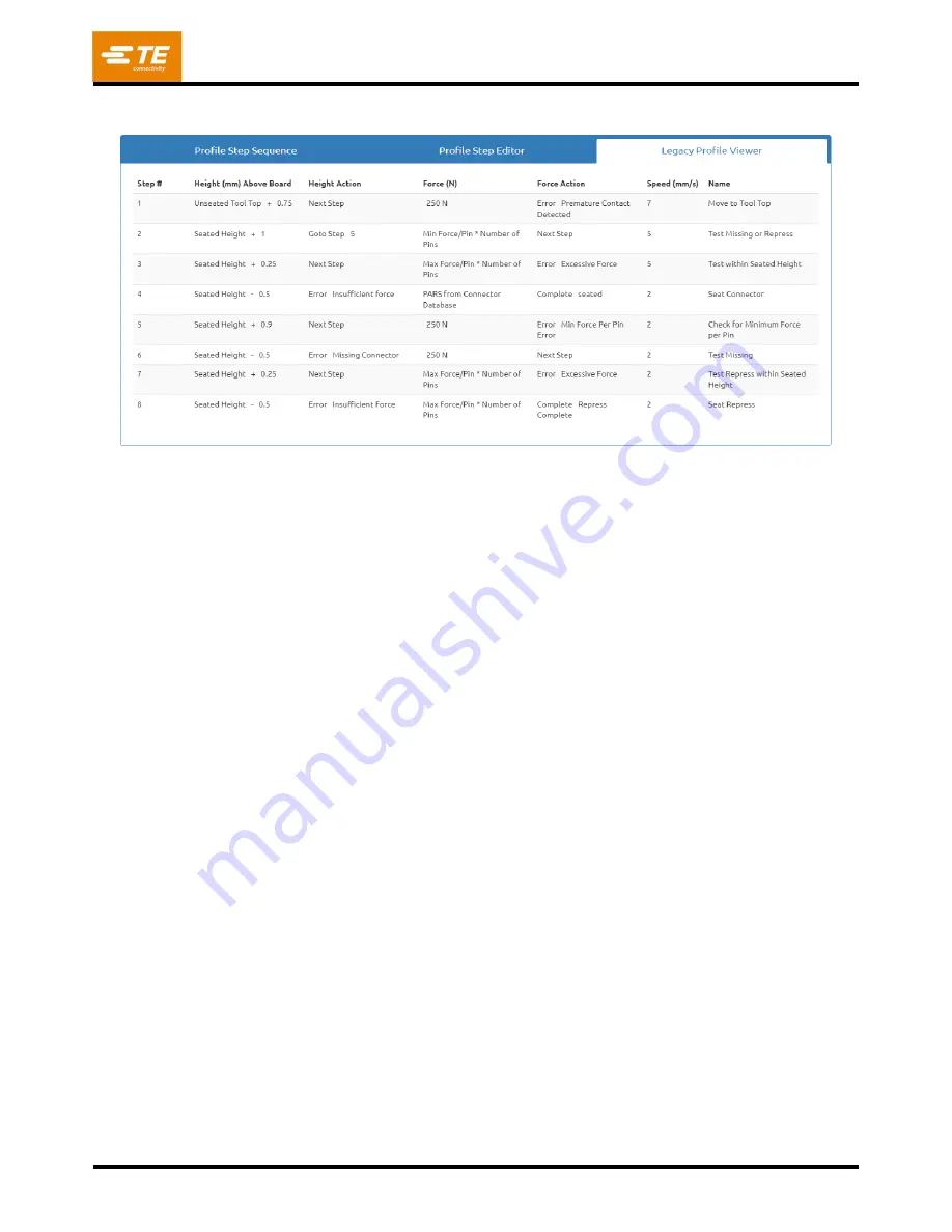
Example: Pressing with PARS (Figure 43)
Figure 43
The screen capture example shown in Figure 43 is a typical PARS press profile. The name at the left end of
each line indicates the action that line will perform. In general, PARS pressing is the preferred method because
it limits excess pressing force but still presses the connector to the board surface. Fragile connectors that
cannot accept any excess force must be pressed to height as described in the example below.
1. Move the head from the tool clearance height (as given in the Tool Database) down to 0.75 mm
[.030 in.] above the unseated top of tool. The speed will ramp linearly from the press “Run Speed”
down to 7 mm [.276 in.] per second. When the height is reached, the sequence will continue on the
next step. If more than 250 Newtons [899 ozf] are detected before the height is reached, terminate
and display error #1, typically “Premature contact detected”.
2. Continue to move down until the connector is 1.0 mm above its seated height. The speed is reduced
to 5 mm/second. This line tests to see if a connector is actually detected. If it is, as indicated by
detecting at least the minimum force per pin (MinFPP), the process continues on the next line. If not,
the process continues on line 5 to attempt a repress of a previously pressed (full or partial press)
connector.
3. Press until the connector is within 0.25 mm of the desired seated height. When this position is
reached, the connector will be within a generally accepted tolerance of seated height. The 0.25 mm
can be adjusted as needed for specific circumstances. If the force exceeds the maximum force per pin
(MaxFPP) before the height is reached, an error message is displayed.
4. The destination of this step will theoretically over press the connector, but the process will actually be
complete as soon as the force reaches the PARS region average force plus an additional percentage
specified in the connector database. The height given simply provides a destination that is not
intended to be reached because the force condition will be satisfied first. If the destination is reached
(on the correct connector) before the PARS force is reached, then there is most likely an error in the
parameters used to calculate the distance relationship between connector, tool, and board surface. If
this occurs, review the tool height, the connector base thickness, the backup fixture thickness, and the
board thickness. Note that a PARS line also monitors for MaxFPP. If MaxFPP is exceeded before
reac
hing the PARS force, then pressing will stop with an “excess force” error. The speed will linearly
slow to 2 mm/second by the target height.
Содержание 2216055
Страница 34: ...409 35001 Rev C 34 of 92 Figure 35 Figure 36 ...
Страница 71: ...409 35001 Rev C 71 of 92 Figure 77 ...
Страница 72: ...409 35001 Rev C 72 of 92 Figure 78 Figure 79 ...
Страница 75: ...409 35001 Rev C 75 of 92 Figure 82 Figure 83 ...


